Toyota Sienna Service Manual: Inspection
1. INSPECT NO. 1 VALVE ROCKER ARM SUBASSEMBLY
(a) Turn the roller by hand to check that it turns smoothly.
HINT: If the roller does not turn smoothly, replace the valve rocker arm sub-assembly.
2. INSPECT VALVE LASH ADJUSTER ASSEMBLY
NOTICE:
|
(a) Place the valve lash adjuster assembly into a container filled with engine oil.
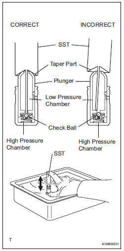
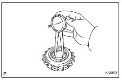
(b) Insert SST's tip into the valve lash adjuster assembly's plunger and use the tip to press down on the check ball inside the plunger.
SST 09276-75010 (c) Squeeze SST and valve lash adjuster assembly together to move the plunger up and down 5 to 6 times.
(d) Check the movement of the plunger and bleed the air
OK: Plunger moves up and down.
| NOTICE: When bleeding air from the high-pressure chamber, make sure that the tip of SST is actually pressing the check ball as shown in the illustration. If the check ball is not pressed, air will not bleed. |
(e) After bleeding the air, remove SST. Then try to quickly and firmly press the plunger with a finger.
OK: Plunger is very difficult to move.
If the result is not as specified, replace the lash adjuster.
3. INSPECT CAMSHAFT
(a) Inspect the camshaft for runout.
(1) Place the camshaft on V-blocks.
(2) Using a dial indicator, measure the circle runout at the center journal.
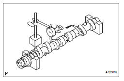
Maximum circle runout: 0.04 mm (0.0016 in.)
If the circle runout is greater than the maximum, replace the camshaft.
HINT: Check the oil clearance after replacing the camshaft.
(b) Using a micrometer, measure the cam lobe height.
Standard cam lobe height
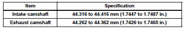
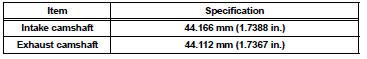
Maximum cam lobe height
(c) Using a micrometer, measure the journal diameter.
Standard journal diameter
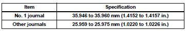
If the journal diameter is not as specified, check the oil clearance.
4. INSPECT CAMSHAFT TIMING GEAR ASSEMBLY
(a) Clamp the camshaft in a vise.
| NOTICE: Be careful not to damage the camshaft in the vise. |
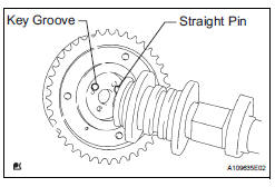
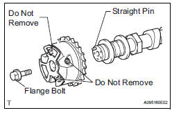
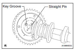
(b) Put the camshaft timing gear assembly and camshaft together by aligning the key groove and straight pin.
(c) Lightly press the camshaft timing gear assembly against the camshaft, and turn the camshaft timing gear assembly. Push further at the position where the pin enters the groove.
| NOTICE: Be sure not to turn the camshaft timing gear in the retard direction (the right angle). |
(d) Check that there is no clearance between the camshaft timing gear assembly's flange and the camshaft.
(e) Tighten the flange bolt with the camshaft timing gear fixed.
Torque: 100 N*m (1,020 kgf*cm, 74 ft.*lbf) (f) Check the lock of the camshaft timing gear assembly.
(1) Clamp the camshaft in a vise, and confirm that the camshaft timing gear assembly is locked.
| NOTICE: Be careful not to damage the camshaft. |
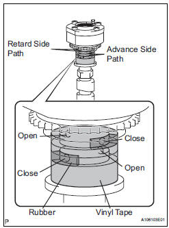
(g) Release the lock pin.
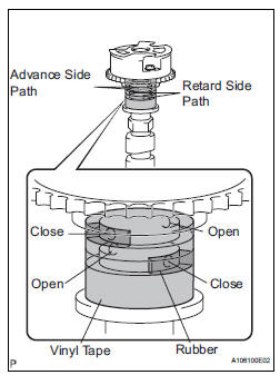
(1) Cover the 4 oil paths of the cam journal with vinyl tape as shown in the illustration.
HINT: 2 advance side paths are provided in the groove of the camshaft. Plug one of the paths with a rubber piece.
(2) Break through the tape of the advance side path and the retard side path on the opposite side to the hole of the advance side path, as shown in the illustration.
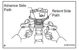
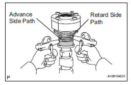
(3) Apply approximately 200 kPa (2.0 kgf/cm2, 28 psi) of air pressure to the 2 broken paths.
| CAUTION: Cover the paths with a piece of cloth when applying pressure to keep oil from splashing. |
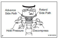
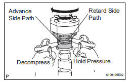
(4) Check that the camshaft timing gear assembly revolves in the advance direction when reducing the air pressure applied to the retard side path.
HINT: This operation releases the lock pin for the most retarded position.
(5) When the camshaft timing gear assembly reaches the most advanced position, release the air pressure from the retard side path and advance side path, in that order.
| NOTICE: Do not release the air pressure from the advance side path first. The gear may abruptly shift in the retard direction and break the lock pin. |
(h) Check for smooth rotation.
(1) Turn the camshaft timing gear assembly within its movable range (21°) 2 or 3 times, but do not turn it to the most retarded position. Make sure that the gear turns smoothly.
| NOTICE: Do not use air pressure to perform the smooth operation check. |
(i) Check the lock in the most retarded position.
(1) Confirm that the camshaft timing gear assembly is locked at the most retarded position.
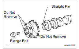
(j) Remove the flange bolt and camshaft timing gear assembly.
NOTICE:
|
5. INSPECT CAMSHAFT TIMING EXHAUST GEAR ASSEMBLY
(a) Clamp the camshaft in a vise.
| NOTICE: Be careful not to damage the camshaft in the vise. |
(b) Put the camshaft timing exhaust gear assembly and camshaft together by aligning the key groove and straight pin.
(c) Lightly press the camshaft timing gear against the camshaft, and turn the camshaft timing gear assembly. Push further at the position where the pin enters the groove.
| NOTICE: Be sure not to turn the camshaft timing exhaust gear in the retard direction (the right angle). |
(d) Check that there is no clearance between the gear's flange and the camshaft.
(e) Tighten the flange bolt with the camshaft timing exhaust gear assembly fixed.
Torque: 100 N*m (1020 kgf*cm, 74 ft.*lbf) (f) Check the camshaft timing exhaust gear lock.
(1) Make sure that the camshaft timing exhaust gear assembly is locked.
(g) Release the lock pin.
(1) Cover the 4 oil paths of the cam journal with vinyl tape as shown in the illustration.
HINT: 4 oil paths are provided in the groove. Plug 2 paths with rubber pieces.
(2) Prick a hole in the tape placed on the advance side path. Prick a hole in the tape placed on the retard side path, on the opposite side to that of the advance side path, as shown in the illustration.
(3) Apply approximately 200 kPa (2.0 kgf/cm2, 28 psi) of air pressure to the 2 broken paths (the advance side path and the retard side path).
| CAUTION: Cover the paths with a piece of cloth when applying pressure to keep oil from splashing. |
(4) Make sure that the camshaft timing exhaust gear turns in the retard direction when reducing the air pressure applied to the advance side path.
HINT: The lock pin is released and the camshaft timing exhaust gear turns in the retard direction.
(5) When the camshaft timing exhaust gear moves to the most retarded position, release the air pressure from the advance side path, and then release the air pressure from the retard side path.
| NOTICE: Be sure to release the air pressure from the advance side path first. If the air pressure of the retard side path is released first, the camshaft timing exhaust gear may abruptly shift in the advance direction and break the lock pin or other parts. |
(h) Check for smooth rotation.
(1) Turn the camshaft timing exhaust gear within its movable range (18.5°) 2 or 3 times, but do not turn it to the most advanced position. Make sure that the gear turns smoothly.
| NOTICE:
When the air pressure is released from the
advance side path and then from the retard
side path, the gear automatically returns to
the most advanced position due to the
advance assist spring operation and locks.
Gradually release the air pressure from the retard side path before performing the smooth rotation check. |
(i) Check the lock at the most advanced position.
(1) Make sure that the camshaft timing exhaust gear is locked at the most advanced position.
(j) Remove the flange bolt and camshaft timing exhaust gear.
NOTICE:
|
6. INSPECT CYLINDER HEAD SET BOLT
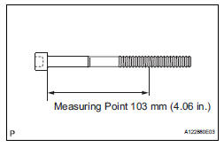
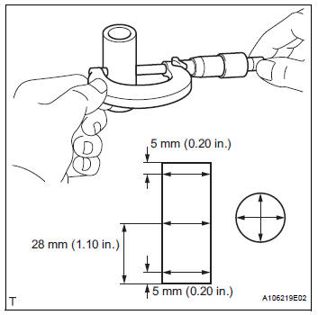
(a) Using vernier calipers, measure the minimum diameter of the elongated thread at the measuring point.
Standard outside diameter: 10.85 to 11.00 mm (0.4272 to 0.4331 in.) Minimum outside diameter: 10.70 mm (0.4213 in.) Measuring Point: 103 mm (4.06 in.)
HINT: If a visual check reveals no excessively thin areas, check the center of the bolt and find the area that has the lowest diameter.
If the diameter is less than the minimum, replace the cylinder head bolt.
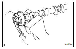
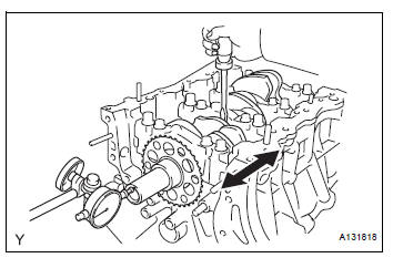
7. INSPECT CHAIN SUB-ASSEMBLY
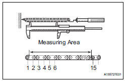
(a) Pull the chain with a force of 147 N (15 kgf, 33 lbf) as shown in the illustration.
(b) Using vernier calipers, measure the length of 15 links
Maximum chain elongation: 136.9 mm (5.390 in.)
| NOTICE:
Perform the measurement at 3 random places.
Use the average of the measurements. |
If the elongation is greater than the maximum, replace the chain.
8. INSPECT NO. 2 CHAIN SUB-ASSEMBLY
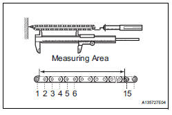
(a) Pull the chain with a force of 147 N (15 kgf, 33 lbf) as shown in the illustration.
(b) Using vernier calipers, measure the length of 15 links.
Maximum chain elongation: 137.6 mm (5.417 in.)
| NOTICE:
Perform the measurement at 3 random places.
Use the average of the measurements. |
If the elongation is greater than the maximum, replace the chain.
9. INSPECT CRANKSHAFT TIMING SPROCKET
(a) Wrap the chain around the sprocket.
(b) Using vernier calipers, measure the sprocket diameter with the chain.
Minimum sprocket diameter (with chain): 61.4 mm (2.417 in.)
HINT: The vernier calipers must contact the chain rollers for the measurement.
If the diameter is less than the minimum, replace the chain and sprocket.
10. INSPECT IDLE SPROCKET ASSEMBLY
(a) Wrap the chain around the sprocket.
(b) Using vernier calipers, measure the sprocket diameter with the chain.
Minimum sprocket diameter (with chain): 61.4 mm (2.417 in.)
HINT: The vernier calipers must contact the chain rollers for the measurement.
If the diameter is less than the minimum, replace the chain and sprocket.
11. INSPECT IDLE GEAR SHAFT OIL CLEARANCE
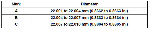
(a) Using a micrometer, measure the idle gear shaft diameter.
Idle gear shaft diameter: 22.987 to 23.000 mm (0.9050 to 0.9055 in.)
(b) Using a caliper gauge, measure the inside diameter of the idle sprocket.
Idle gear inside diameter: 23.020 to 23.030 mm (0.9063 to 0.9067 in.) (c) Subtract the idle gear shaft diameter measurement from the idle sprocket inside diameter measurement.
Standard oil clearance: 0.020 to 0.043 mm (0.0008 to 0.0017 in.) Maximum oil clearance: 0.093 mm (0.0037 in.) If the thrust oil clearance is greater than the maximum, replace the idle gear shaft and idle sprocket.
12. INSPECT NO. 1 CHAIN TENSIONER ASSEMBLY
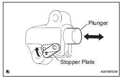
(a) Move the stopper plate upward to release the lock.
Push the plunger and check that it moves smoothly.
If necessary, replace the No. 1 chain tensioner assembly.
13. INSPECT NO. 2 CHAIN TENSIONER ASSEMBLY
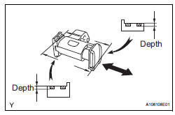
(a) Check that the plunger moves smoothly.
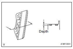
(b) Measure the worn depth of the No. 2 chain tensioner.
Maximum depth: 0.9 mm (0.035 in.) If the depth is greater than the maximum, replace the No. 2 chain tensioner assembly.
14. INSPECT NO. 3 CHAIN TENSIONER ASSEMBLY
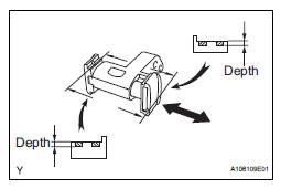
(a) Check that the plunger moves smoothly.
(b) Measure the worn depth of the No. 3 chain tensioner.
Maximum depth: 0.9 mm (0.035 in.)
If the depth is greater than the maximum, replace the No. 3 chain tensioner assembly.
15. INSPECT CHAIN TENSIONER SLIPPER
(a) Measure the worn depth of the chain tensioner slipper.
Maximum depth: 1.0 mm (0.039 in.) If the depth is greater than the maximum, replace the chain tensioner slipper.
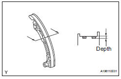
16. INSPECT NO. 1 CHAIN VIBRATION DAMPER
(a) Measure the worn depth of the No. 1 chain vibration damper.
Maximum depth: 1.0 mm (0.039 in.) If the depth is greater than the maximum, replace the No. 1 chain vibration damper.
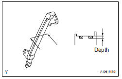
17. INSPECT NO. 2 CHAIN VIBRATION DAMPER
(a) Measure the worn depth of the No. 2 chain vibration damper.
Maximum depth: 1.0 mm (0.039 in.) If the depth is greater than the maximum, replace the No. 2 chain vibration damper.
(a) Measure the worn depth of the No. 2 chain vibration damper.
Maximum depth: 1.0 mm (0.039 in.) If the depth is greater than the maximum, replace the No. 2 chain vibration damper.
18. INSPECT CYLINDER HEAD SUB-ASSEMBLY
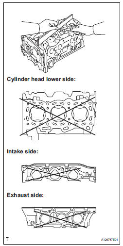
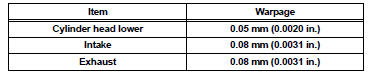
(a) Using a precision straight edge and feeler gauge, measure the warpage of the contact surface of the cylinder block and manifolds.
Standard warpage
Maximum warpage
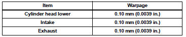
If the warpage is greater than the maximum, replace the cylinder head assembly.
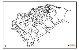
(b) Using a dye penetrant, check the intake ports, exhaust ports and cylinder surface for cracks.
If cracked, replace the cylinder head assembly.
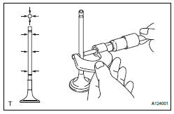
19. INSPECT INTAKE VALVE
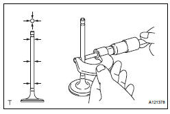
(a) Using a micrometer, measure the diameter of the valve stem.
Valve stem diameter: 5.470 to 5.485 mm (0.2154 to 0.2159 in.) If the valve stem is not as specified, check the oil clearance.
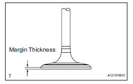
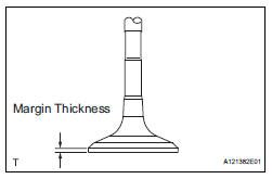
(b) Using vernier calipers, measure the valve head margin thickness.
Standard margin thickness: 1.0 mm (0.039 in.) Minimum margin thickness: 0.5 mm (0.0197 in.) If the margin thickness is less than the minimum, replace the intake valve.
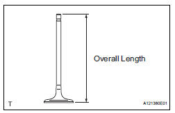
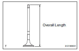
(c) Using vernier calipers, measure the valve's overall length.
Standard overall length: 105.85 mm (4.1673 in.) Minimum overall length: 105.35 mm (4.1476 in.) If the overall length is less than the minimum, replace the intake valve.
20. INSPECT EXHAUST VALVE
(a) Using a micrometer, measure the diameter of the valve stem.
Valve stem diameter: 5.465 to 5.480 mm (0.2151 to 0.2157 in.) If the valve stem is not as specified, check the oil clearance.
(b) Using vernier calipers, measure the valve head margin thickness.
Standard margin thickness: 1.0 mm (0.039 in.) Minimum margin thickness: 0.5 mm (0.0197 in.) If the margin thickness is less than the minimum, replace the exhaust valve.
(c) Using vernier calipers, measure the valve's overall length.
Standard overall length: 110.40 mm (4.3464 in.) Minimum overall length: 109.90 mm (4.3268 in.) If the overall length is less than the minimum, replace the exhaust valve.
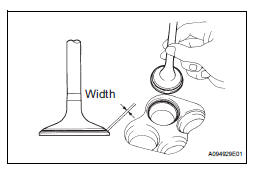
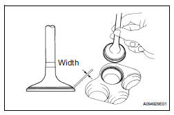
21. INSPECT INTAKE VALVE SEAT
(a) Apply a light coat of Prussian blue to the valve face.
(b) Lightly press the valve face against the valve seat.
(c) Check the valve face and valve spring seat by using the following procedure:
(1) If Prussian blue appears around the entire valve face, the valve face is concentric. If not, replace the valve.
(2) If Prussian blue appears around the entire valve seat, the guide and valve face are concentric. If not, resurface the valve spring seat.
(3) Check that the valve spring seat contacts in the middle of the valve face with the width between 1.1 and 1.5 mm (0.043 and 0.059 in.).
22. INSPECT EXHAUST VALVE SEAT
(a) Apply a light coat of Prussian blue to the valve face.
(b) Lightly press the valve face against the valve spring seat.
(c) Check the valve face and valve spring seat by using the following procedure:
(1) If Prussian blue appears around the entire valve face, the valve face is concentric. If not, replace the valve.
(2) If Prussian blue appears around the entire valve seat, the guide and valve face are concentric. If not, resurface the valve spring seat.
(3) Check that the valve spring seat contacts in the middle of the valve face with the width between 1.1 and 1.5 mm (0.043 and 0.059 in.).
23. REPAIR INTAKE VALVE SEAT
NOTICE:
|
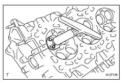
(a) Using a 45° cutter, resurface the valve spring seat so that the valve spring seat width is more than the specification.
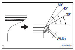
(b) Using 30° and 60° cutters, correct the valve seat so that the valve contacts the entire circumference of the seat. The contact should be in the center of the valve spring seat, and the valve spring seat width should be maintained within the specified range around the entire circumference of the seat.
Width: 1.1 to 1.5 mm (0.043 to 0.059 in.)
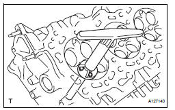
(c) Handrub the valve and valve seat with an abrasive compound.
(d) Check the valve seating position.
24. REPAIR EXHAUST VALVE SEAT
NOTICE:
|
(a) Using a 45° cutter, resurface the valve spring seat so that the valve spring seat width is more than the specification.
(b) Using 30° and 75° cutters, correct the valve seat so that the valve contacts the entire circumference of the seat. The contact should be in the center of the valve seat, and the valve seat width should be maintained within the specified range around the entire circumference of the seat.
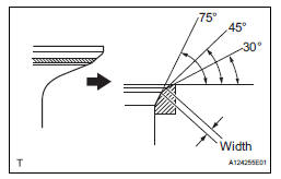
Width: 1.1 to 1.5 mm (0.043 to 0.059 in.)
(c) Handrub the valve and valve seat with an abrasive compound.
(d) Check the valve seating position.
25. INSPECT INNER COMPRESSION SPRING
(a) Using vernier calipers, measure the free length of the inner compression spring.
Free length: 45.46 mm (1.7898 in.) If the free length is not as specified, replace the inner compression spring.
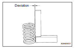
(b) Using a steel square, measure the deviation of the inner compression spring.
Maximum deviation: 1.0 mm (0.039 in.) Maximum angle (reference): 2° If the deviation is greater than the maximum, replace the inner compression spring.
26. INSPECT VALVE GUIDE BUSH OIL CLEARANCE
(a) Using a caliper gauge, measure the inside diameter of the valve guide bush.
Bush inside diameter: 5.510 to 5.530 mm (0.2169 to 0.2177 in.) (b) Subtract the valve stem diameter measurement from the valve guide bush inside diameter measurement.
Standard clearance
Maximum oil clearance
For intake side: If the clearance is greater than the maximum, replace the intake valve and intake valve guide bush.
For exhaust side: If the clearance is greater than the maximum, replace the exhaust valve and exhaust valve guide bush.
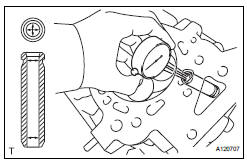
27. INSPECT CAMSHAFT THRUST CLEARANCE
(a) Inspect the bank 1 camshaft thrust clearance.
(1) Install the bank 1 camshaft (See page EM- 126).
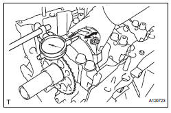
(2) Using a dial indicator, measure the thrust clearance while moving the camshaft back and forth.
Standard thrust clearance: 0.08 to 0.13 mm (0.0031 to 0.0051 in.) Maximum thrust clearance: 0.15 mm (0.006 in.)
If the thrust clearance is greater than the maximum, replace the cylinder head. If the thrust surface is damaged, replace the camshaft.
(b) Inspect the bank 2 camshaft thrust clearance.
(1) Install the bank 2 camshaft (See page EM- 126).
(2) Using a dial indicator, measure the thrust clearance while moving the camshaft back and forth.
Standard thrust clearance: 0.08 to 0.13 mm (0.0031 to 0.0051 in.) Maximum thrust clearance: 0.15 mm (0.006 in.)
If the thrust clearance is greater than the maximum, replace the cylinder head. If the thrust surface is damaged, replace the camshaft.
28. INSPECT CAMSHAFT OIL CLEARANCE
(a) Clean the camshaft bearing caps, camshaft housing and camshaft journals.
(b) Place the camshafts on the camshaft housing.
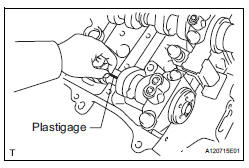
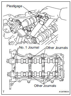
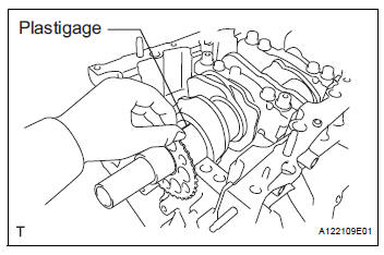
(c) Lay a strip of Plastigage across each of the camshaft journals.
(d) Install the camshaft bearing caps (See page EM- 126).
| NOTICE: Do not turn the camshaft. |
(e) Remove the camshaft bearing caps (See page EM- 76).
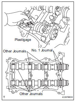
(f) Measure the Plastigage at its widest point.
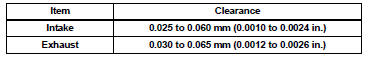
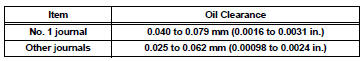
Standard oil clearance
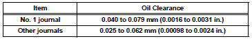
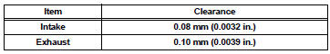
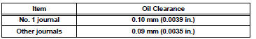
Maximum oil clearance
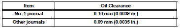
If the oil clearance is greater than the maximum, replace the camshaft. If necessary, replace the camshaft housing.
(g) Clean the camshaft bearing caps, camshaft housing and camshaft journals.
(h) Place the camshafts on the camshaft housing.
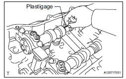
(i) Lay a strip of Plastigage across each of the camshaft journals.
(j) Install the bearing caps (See page EM-126).
| NOTICE: Do not turn the camshaft. |
(k) Remove the bearing caps (See page EM-76).
(l) Measure the Plastigage at its widest point.
Standard oil clearance
Maximum oil clearance
If the oil clearance is greater than the maximum, replace the camshaft. If necessary, replace the camshaft housing.
29. INSPECT CONNECTING ROD THRUST CLEARANCE
(a) Install the connecting rod cap (See page EM-126).
(b) Using a dial indicator, measure the thrust clearance while moving the connecting rod back and forth.
Standard thrust clearance: 0.15 to 0.40 mm (0.0059 to 0.0157 in.) Maximum thrust clearance: 0.50 mm (0.020 in.) If the thrust clearance is greater than the maximum, replace the connecting rod assemblies as necessary. If necessary, replace the crankshaft.
30. INSPECT CONNECTING ROD OIL CLEARANCE
(a) Clean the crank pin and bearing.
(b) Check the crank pin and bearing for pitting and scratches.
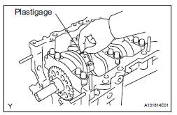
(c) Lay a strip of Plastigage on the crank pin.
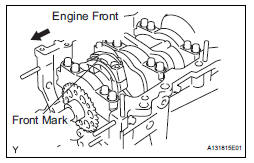
(d) Check that the front mark of the connecting rod cap is facing forward.
(e) Install the connecting rod cap (See page EM-126).
| NOTICE: Do not turn the crankshaft. |
(f) Remove the 2 bolts and connecting rod cap (See page EM-76).
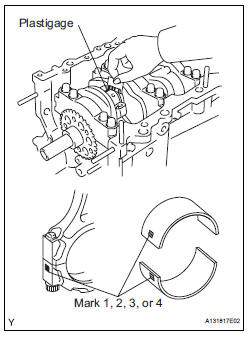
(g) Measure the Plastigage at its widest point.
Standard oil clearance: 0.045 to 0.067 mm (0.0018 to 0.0026 in.) Maximum oil clearance: 0.070 mm (0.0028 in.)
If the oil clearance is greater than the maximum, replace the connecting rod bearings. If necessary, inspect the crankshaft.
HINT: If replacing a bearing, replace it with one that has the same number as its respective connecting rod cap. Each bearing's standard thickness is indicated by a 1, 2, 3 or 4 mark on its surface.
Connecting rod diameter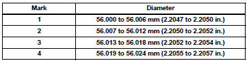
Connecting rod bearing center wall thickness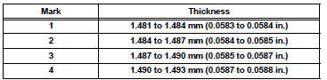
Crankshaft pin diameter: 52.992 to 53.000 mm (2.0863 to 2.0866 in.)
| NOTICE: Completely remove the Plastigage after the measurement. |
31. INSPECT CRANKSHAFT THRUST CLEARANCE
(a) Install the crankshaft bearing cap (See page EM- 126).
(b) Using a dial indicator, measure the thrust clearance while prying the crankshaft back and forth with a screwdriver.
Standard thrust clearance: 0.04 to 0.24 mm (0.0016 to 0.0094 in.) Maximum thrust clearance: 0.30 mm (0.0118 in.)
If the thrust clearance is greater than the maximum, replace the thrust washers as a set. If necessary, replace the crankshaft.
Thrust washer thickness: 2.43 to 2.48 mm (0.0957 to 0.0976 in.)
32. INSPECT CYLINDER BLOCK FOR WARPAGE
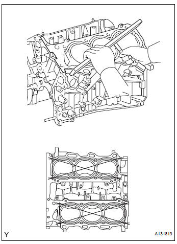
(a) Using a precision straight edge and feeler gauge, measure the warpage of the contact surface of the cylinder head gasket.
Maximum warpage: 0.07 mm (0.0028 in.)
If the warpage is greater than the maximum, replace the cylinder block.
33. INSPECT CYLINDER BORE
(a) Visually check the cylinder for vertical scratches.
If deep scratches are present, rebore all the 6 cylinders. If necessary, replace the cylinder block.
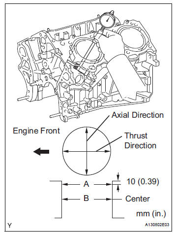
(b) Using a cylinder gauge, measure the cylinder bore diameter at positions A and B in the thrust and axial directions.
Standard diameter: 94.000 to 94.012 mm (3.7008 to 3.7013 in.) Maximum diameter: 94.200 mm (3.7087 in.)
If the average diameter of 4 positions is greater than the maximum, replace the cylinder block.
34. INSPECT PISTON SUB-ASSEMBLY WITH PIN
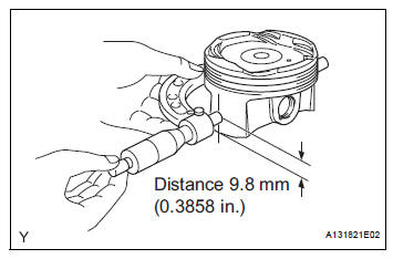
(a) Using a micrometer, measure the piston diameter at right angles to the piston center line where the distance from the piston end is as specified.
Distance: 9.8 mm (0.3858 in.) Standard diameter: 93.960 to 93.980 mm (3.6992 to 3.7000 in.) Maximum diameter: 93.830 mm (3.6941 in.)
35. INSPECT PISTON OIL CLEARANCE
(a) Measure the cylinder bore diameter in the thrust directions.
(b) Subtract the piston diameter measurement from the cylinder bore diameter measurement.
Standard oil clearance: 0.020 to 0.052 mm (0.0008 to 0.0020 in.) Maximum oil clearance: 0.060 mm (0.0024 in.)
If the oil clearance is greater than the maximum, replace all the pistons. If necessary, replace the cylinder block.
36. INSPECT RING GROOVE CLEARANCE
(a) Using a feeler gauge, measure the clearance between a new piston ring and the wall of the ring groove.
Ring groove clearance 
If the clearance is not as specified, replace the piston.
37. INSPECT PISTON RING END GAP
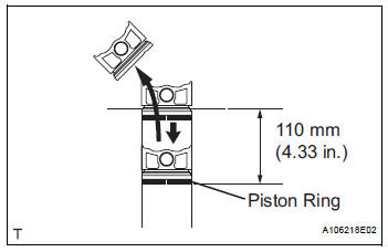
(a) Insert the piston ring into the cylinder bore.
(b) Using a piston, push the piston ring a little beyond the bottom of the ring travel, 110 mm (4.33 in.) from the top of the cylinder block.
(c) Using a feeler gauge, measure the end gap.
Standard end gap 
Maximum end gap 
If the end gap is greater than the maximum, replace the piston ring. If the end gap is greater than the maximum even with a new piston ring, rebore all the 6 cylinders or replace the cylinder block.
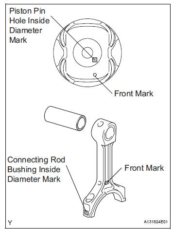
38. INSPECT PISTON PIN OIL CLEARANCE
(a) Using a caliper gauge, measure the inside diameter of the piston pin hole.
Piston pin hole inside diameter
(b) Using a micrometer, measure the piston pin diameter.
Piston pin diameter 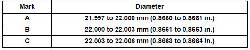
(c) Subtract the piston pin diameter measurement from the piston pin hole diameter measurement.
Standard oil clearance: 0.001 to 0.007 mm (0.00004 to 0.00028 in.) Maximum oil clearance: 0.015 mm (0.0006 in.)
If the oil clearance is greater than the maximum, replace the piston and piston pin as a set.
(d) Using a caliper gauge, measure the inside diameter of the connecting rod bushing.
Bushing inside diameter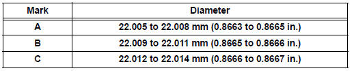
(e) Subtract the piston pin diameter measurement from the bushing inside diameter measurement.
Standard oil clearance: 0.005 to 0.011 mm (0.0002 to 0.0004 in.) Maximum oil clearance: 0.030 mm (0.0012 in.)
If the oil clearance is greater than the maximum, replace the bushing. If necessary, replace the connecting rod and piston pin as a set.
39. INSPECT CONNECTING ROD
(a) Using a rod aligner and feeler gauge, check the connecting rod alignment.
(1) Check for out-of-alignment.
Maximum out-of-alignment: 0.05 mm (0.0020 in.) per 100 mm (3.94 in.)
If the out-of-alignment is greater than the maximum, replace the connecting rod assembly.
(2) Check for twist.
Maximum twist: 0.15 mm (0.0059 in.) per 100 mm (3.94 in.)
If the twist is greater than the maximum, replace the connecting rod assembly.
40. INSPECT CONNECTING ROD BOLT
(a) Using vernier calipers, measure the tension portion diameter of the bolt.
Standard diameter: 7.2 to 7.3 mm (0.284 to 0.287 in.) Minimum diameter: 7.0 mm (0.276 in.) If the diameter is less than the minimum, replace the bolt.
41. INSPECT CRANKSHAFT
(a) Inspect for circle runout.
(1) Clean the crank journal.
(2) Place the crankshaft on V-blocks.
(3) Using a dial indicator, measure the circle runout at the center journal.
Maximum circle runout: 0.06 mm (0.0024 in.)
If the circle runout is greater than the maximum, replace the crankshaft.

(b) Inspect the main journals.
(1) Using a micrometer, measure the diameter of each main journal.
Standard journal diameter: 60.988 to 61.000 mm (2.4011 to 2.4016 in.)
If the diameter is not as specified, check the oil clearance. If necessary, replace the crankshaft.
(2) Check each main journal for taper and out-ofround as shown in the illustration.
Maximum taper and out-of-round: 0.02 mm (0.0008 in.)
If the taper and out-of-round is greater than the maximum, replace the crankshaft.
(c) Inspect the crank pin.
(1) Using a micrometer, measure the diameter of each crank pin.
Crankshaft pin diameter: 52.992 to 53.000 mm (2.0863 to 2.0866 in.)
If the diameter is not as specified, check the oil clearance. If necessary, replace the crankshaft.
(2) Check each crank pin for taper and out-ofround as shown in the illustration.
Maximum taper and out-of-round: 0.02 mm (0.0008 in.)
If the taper and out-of-round is greater than the maximum, replace the crankshaft.
42. INSPECT CRANKSHAFT OIL CLEARANCE
(a) Check the crank journal and bearing for pitting and scratches.
(b) Install the crankshaft bearing (See page EM-126).
(c) Place the crankshaft on the cylinder block.
(d) Lay a strip of Plastigage across each journal.
(e) Examine the front marks and numbers and install the bearing caps on the cylinder block.
HINT: A number is marked on each main bearing cap to indicate the installation position.
(f) Install the main bearing cap (See page EM-126).
| NOTICE: Do not turn the crankshaft. |
(g) Remove the main bearing caps (See page EM-76).
(h) Measure the Plastigage at its widest point.
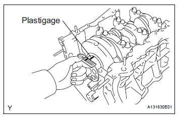
Standard oil clearance: 0.026 to 0.047 mm (0.0010 to 0.0019 in.) Maximum oil clearance: 0.050 mm (0.0020 in.)
If the oil clearance is greater than the maximum, replace the bearings. If necessary, replace the crankshaft.
| NOTICE: Completely remove the Plastigage after the measurement. |
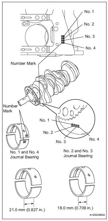
(i) If replacing a bearing, replace it with one having the same number. If the number of the bearing cannot be determined, select the correct bearing by adding together the numbers imprinted on the cylinder block and crankshaft, then refer to the table below for the appropriate bearing number. There are 5 sizes of standard bearings, marked "1", "2", "3", "4" and "5" accordingly.
Journal bearings: 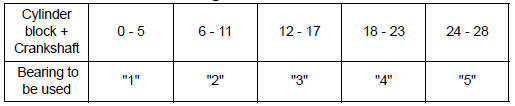
HINT:
EXAMPLE: Cylinder block "11" + Crankshaft "06" = Total number 17 (Use bearing "3")
Crankshaft main journal diameter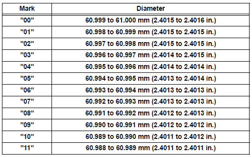
Standard upper bearing center wall thickness
(No. 1 and No. 4 journal) 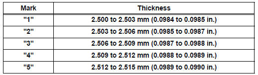
Standard lower bearing center wall thickness
(No. 1 and No. 4 journal) 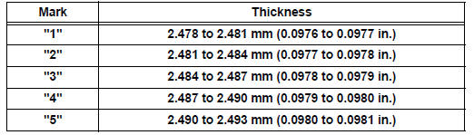
Standard upper bearing center wall thickness
(No. 2 and No. 3 journal) 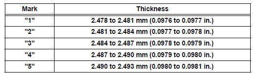
Standard lower bearing center wall thickness
(No. 2 and No. 3 journal)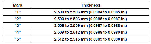
43. INSPECT CRANKSHAFT BEARING CAP SET BOLT
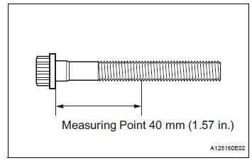
(a) Using vernier calipers, measure the minimum diameter of the compressed thread at the measuring point.
Standard diameter: 10.8 to 11.0 mm (0.4252 to 0.4331 in.) Minimum diameter: 10.7 mm (0.4213 in.) Measuring Point: 40 mm (1.57 in.)
If the diameter is less than the minimum, replace the bolt.
 Disassembly
1. Remove oil filler cap sub-assembly
(A) remove the oil filler cap sub-assembly and oil filler
gasket.
2. REMOVE SPARK PLUG
(a) Remove the spark plugs.
3. REMOVE OIL PAN DRAIN PLUG
(a) Remove t ...
 Reassembly
1. INSTALL STRAIGHT PIN
(a) Using a plastic hammer, tap in new straight pins to
the cylinder block.
Standard protrusion
2. INSTALL STUD BOLT
(a) Using E8 and E10 "TORX" sockets, i ...
Other materials:
System check
HINT:
Performing a SYSTEM CHECK enables the system,
which consists of the multiple actuators, to be operated
without removing any parts. In addition, it can show
whether or not any DTCs are set, and can detect
potential malfunctions in the system. The SYSTEM
CHECK can be performed with an inte ...
Illumination Circuit
DESCRIPTION
Power is supplied to the radio receiver and steering pad switch illumination
when the light control switch is
in the TAIL or HEAD position.
WIRING DIAGRAM
INSPECTION PROCEDURE
NOTICE:
The vehicle is equipped with an SRS (Supplemental Restraint System) which
includes
compon ...
Screen Flicker or Color Distortion
INSPECTION PROCEDURE
1 CHECK DISPLAY SETTING
Enter the display adjustment screen by pressing the
"DISPLAY" switch.
Reset display settings (contrast, brightness) and check
that the screen appears normal
Press the "INFO" switch and then select "S ...
