Toyota Sienna Service Manual: Inspection
1. Inspect no. 3 Intake air control valve assembly
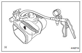
(A) inspect actuator operation.
(1) With 26.7 Kpa (200 mm hg, 7.9 In. Hg) of vacuum applied to the actuator, check that the actuator rod moves.
(2) One minute after applying the vacuum, check that the actuator rod does not return.
(3) If the operation is not as specified, replace the no. 3 Intake air control valve.
Installation
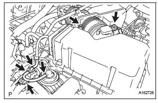
1. INSTALL NO. 3 INTAKE AIR CONTROL VALVE ASSEMBLY
(a) Engage the 2 claws and install the No. 3 intake air control valve assembly.
2. INSTALL AIR CLEANER CAP SUB-ASSEMBLY
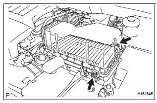
(a) Install the air cleaner filter element, and air cleaner cap sub-assembly with the 2 bolts.
Torque: 5.0 N*m (50 kgf*cm, 44 in.*lbf)
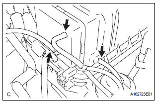
(b) Connect the 3 vacuum hoses.
(c) Tighten the bolt, connect the 2 connectors, and install the 2 vacuum hoses.
3. INSTALL NO. 2 AIR CLEANER INLET (See page EM- 60)
 Removal
1. Remove no. 2 Air cleaner inlet (see page em-
28)
2. Remove air cleaner cap sub-assembly
(a) Disconnect the 3 vacuum hoses.
(b) Loosen the bolt, disconnect the 2 connectors, and
remove ...
 Vacuum tank
On-vehicle inspection
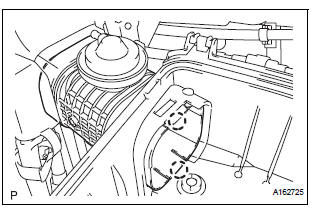
1. Inspect air cleaner cap sub-assembly
(A) check that air flows from port b to port a.
(B) apply 60 kpa (450 mm hg, 18 in. Hg) of vacuum to
port b. Check that there is ...
Other materials:
Definition of terms
Terms
Definitions
Monitor Description
Description of what ECM monitors and how to detect malfunctions
(monitoring purpose and details).
Related DTCs
A group of diagnostic trouble codes that are output by ECM based on
the same malfunction detection lo ...
Release Actuator Circuit
DESCRIPTION
The fold seat control ECU receives a switch operation signal from the fold
seat switch and activates the
release actuator. The release actuator releases the lock of the stowed seat
based on a drive voltage
received from the ECU.
WIRING DIAGRAM
INSPECTION PROCEDURE
1 INSPECT ...
On-vehicle inspection
1. INSPECT FRONT PASSENGER AIRBAG ASSEMBLY
(VEHICLE NOT INVOLVED IN COLLISION)
Perform a diagnostic system check.
With the front passenger airbag assembly installed
on the vehicle, perform a visual check. If there are
any defects as mentioned below, replace the
instrumen ...
