Toyota Sienna Service Manual: Installation
1. INSTALL REAR DIFFERENTIAL DRIVE PINION BEARING SPACER
(a) Install a new bearing spacer.
2. INSTALL REAR DRIVE PINION FRONT TAPERED ROLLER BEARING
(a) Install the tapered roller bearing.
3. INSTALL REAR DIFFERENTIAL DRIVE PINION OIL SLINGER
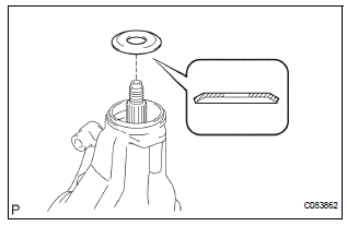
(a) Install the oil slinger, as shown in the illustration.
4. INSTALL REAR DIFFERENTIAL CARRIER OIL SEAL
(a) Using SST and a hammer, install a new oil seal.
SST 09554-22010 Oil seal drive in depth: 2.0 +- 0.3 mm (0.079 +- 0.012 in.)
(b) Coat MP grease to the oil seal lip.
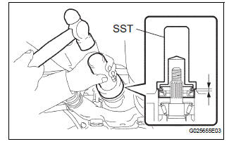
5. INSTALL REAR DRIVE PINION COMPANION FLANGE SUB-ASSEMBLY
(a) Using SST, install the companion flange on the shaft.
SST 09950-30012 (09951-03010, 09953-03010, 09954-03010, 09955-03030, 09956-03020)
NOTICE: Apply hypoid gear oil to the SST center bolt tip and threads before use.
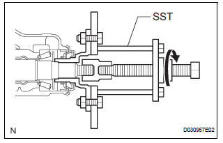
6. INSTALL REAR DRIVE PINION NUT
(a) Coat the threads of a new nut with hypoid gear oil LSD.
(b) Using SST to hold the flange, torque the nut.
SST 09330-00021 Torque: 108 N*m (1,100 kgf*cm, 80 ft.*lbf)
7. INSPECT DIFFERENTIAL DRIVE PINION PRELOAD
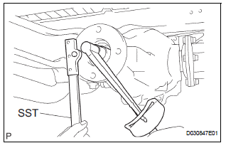
(a) Inspect differential drive pinion preload (See page DF-31).
(b) Using a chisel and a hammer, stake the drive pinion nut.
8. INSTALL REAR DIFFERENTIAL DRAIN PLUG
(a) Using a hexagon wrench (10 mm), install the filler plug with a new gasket.
Torque: 49 N*m (500 kgf*cm, 36 ft.*lbf)
9. ADD DIFFERENTIAL OIL
(a) Fill the rear differential carrier assembly with hypoid gear oil.
10. INSPECT DIFFERENTIAL OIL
HINT: (See page DF-3)
11. INSTALL REAR DIFFERENTIAL FILLER PLUG
(a) Using a hexagon wrench (10 mm), install the filler plug with a new gasket.
Torque: 49 N*m (500 kgf*cm, 36 ft.*lbf)
12. INSTALL PROPELLER WITH CENTER BEARING SHAFT ASSEMBLY
(a) Install propeller with center bearing shaft assembly (See page PR-9).
(b) Fully tighten propeller with center bearing shaft assembly (See page PR-10).
13. INSTALL EXHAUST PIPE ASSEMBLY
HINT: (See page EX-10)
14. INSPECT FOR EXHAUST GAS LEAK
HINT: (See page EX-12)
 Removal
1. REMOVE FRONT EXHAUST PIPE ASSEMBLY
HINT:
(See page EX-8)
2. REMOVE PROPELLER WITH CENTER BEARING
SHAFT ASSEMBLY
HINT:
(See page PR-3)
3. REMOVE REAR DIFFERENTIAL FILLER PLUG
(a) Using a hex ...
 Rear differential carrier assembly
Components
...
Other materials:
Monitor drive pattern
1. MONITOR DRIVE PATTERN FOR ECT TEST
(a) Perform this drive pattern as one method to
simulate the detection conditions of the ECT
malfunctions. (The DTCs may not be detected due
the actual driving conditions. And some codes may
not be detected through this drive pattern.)
HINT:
Preparation f ...
Throttle Actuator Control Motor Circuit
DESCRIPTION
The throttle actuator is operated by the ECM and opens and closes the
throttle valve using gears.
The opening angle of the throttle valve is detected by the Throttle Position
(TP) sensor, which is mounted
on the throttle body. The TP sensor provides feedback to the ECM. This ...
Reassembly
1. INSTALL NO. 1 SEAT CUSHION FRAME SUBASSEMBLY
LH
Install the seat cushion frame with the bolt.
Torque: Except 7-Passenger RH, M8 bolt
20.6 N*m (210 kgf*cm, 15 ft.*lbf)
M10 bolt
41 N*m (418 kgf*cm, 30 ft.*lbf)
2. INSTALL RECLINING CONTROL LINK SUBASSEMBLY
LH
Install ...
