Toyota Sienna Service Manual: Installation
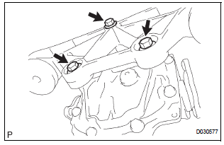
1. INSTALL NO. 1 REAR DIFFERENTIAL SUPPORT
(a) Install the No. 1 rear differential support to the rear differential carrier assembly with the 2 bolts and 2 nuts.
Torque: 85 N*m (867 kgf*cm, 63 ft.*lbf)
HINT: Hold the bolt and tighten the nut.
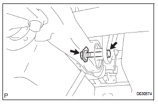
2. INSTALL REAR DIFFERENTIAL DYNAMIC DAMPER
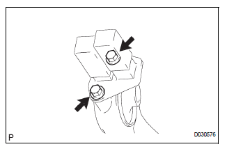
(a) Install the rear differential dynamic damper to the No. 1 rear differential support with the 2 bolts.
Torque: 20 N*m (204 kgf*cm, 15 ft.*lbf)
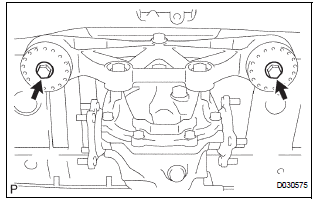
3. INSTALL REAR DIFFERENTIAL SUPPORT ASSEMBLY
(a) Install the rear differential support assembly to rear differential carrier assembly with the 3 bolts.
Torque: 100 N*m (1,020 kgf*cm, 74 ft.*lbf)
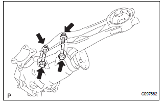
4. INSTALL REAR DIFFERENTIAL CARRIER ASSEMBLY
(a) Jack up the rear differential carrier assembly.
(b) Install the rear differential carrier assembly with the 2 bolts.
Torque: 106 N*m (1,081 kgf*cm, 78 ft.*lbf)
(c) Connect the No. 1 rear differential support with the bolt and nut.
Torque: 95 N*m (969 kgf*cm, 70 ft.*lbf)
HINT: Tighten the bolt.
5. INSTALL REAR DRIVE SHAFT ASSEMBLY LH
HINT: Install procedure of RH side is the same as that of LH side. (See page DS-26)
6. INSTALL REAR AXLE SHAFT NUT LH
HINT: Install procedure of RH side is the same as that of LH side. (See page DS-26)
7. INSTALL REAR SPEED SENSOR LH
HINT: Install procedure of RH side is the same as that of LH side. (See page DS-26)
8. INSTALL PROPELLER WITH CENTER BEARING SHAFT ASSEMBLY (See page PR-9)
9. FULLY TIGHTEN PROPELLER WITH CENTER BEARING SHAFT ASSEMBLY (See page PR-10)
10. INSTALL REAR DIFFERENTIAL DRAIN PLUG
(a) Using a hexagon wrench (10 mm), install the drain plug with a new gasket.
Torque: 49 N*m (500 kgf*cm, 36 ft.*lbf)
11. ADD DIFFERENTIAL OIL
(a) Fill the rear differential carrier assembly with hypoid gear oil.
12. INSPECT DIFFERENTIAL OIL
HINT: (See page DF-3)
13. INSTALL REAR DIFFERENTIAL FILLER PLUG
(a) Using a hexagon wrench (10 mm), install the filler plug with a new gasket.
Torque: 49 N*m (500 kgf*cm, 36 ft.*lbf)
14. INSTALL REAR WHEEL Torque: 103 N*m (1,050 kgf*cm, 76 ft.*lbf)
15. INSTALL EXHAUST PIPE ASSEMBLY
HINT: (See page EX-10)
16. INSPECT FOR EXHAUST GAS LEAK
HINT: (See page EX-12)
17. INSPECT AND ADJUST REAR WHEEL ALIGNMENT
HINT: (See page SP-4)
18. INSPECT ABS SPEED SENSOR SIGNAL
HINT: (See page BC-3)
 Removal
1. Remove rear wheel
2. Remove exhaust pipe assembly
Hint:
(see page ex-8)
3. Remove propeller with center bearing
shaft assembly
Hint:
(see page pr-3)
4. REMOVE REAR DIFFERENTIAL FILLER PLUG
...
 Rear differential carrier
COMPONENTS
...
Other materials:
SRS Warning Light Remains ON
DESCRIPTION
The SRS warning light is located on the combination meter assembly.
When the SRS is normal, the SRS warning light comes on for approximately 6
seconds after the ignition
switch is turned from the LOCK position to ON position, and then goes off
automatically.
If there is a mal ...
Removal
HINT:
On the RH side, use the same procedures as on the LH side.
1. REMOVE SLIDE DOOR
Remove the rear door scuff plate (See page IR-7).
Remove the back door scuff plate (See page ED-
214).
Remove the quarter trim panel (See page IR-9).
Remove the upper rail cushion from the rail up ...
Fuel Pump Control Circuit
DESCRIPTION
The FUEL PUMP relay switches the fuel pump speed according to the engine
conditions. The fuel pump
operates when the ECM receives the starter-operating signal (STA) and
crankshaft-rotating signal (NE).
The FUEL PUMP relay is turned ON while the engine is idling or operating at l ...
