Toyota Sienna Service Manual: Installation
1. INSTALL FRONT SHOCK ABSORBER WITH COIL SPRING
(a) Install the front shock absorber with coil spring as shown in the illustration.
(b) Install the 3 nuts to the upper side of the front shock absorber with coil spring.
Torque: 80 N*m (816 kgf*cm, 59 ft.*lbf)
(c) Install the 2 bolts and 2 nuts to the lower side of the front shock absorber with coil spring.
Torque: 210 N*m (2,140 kgf*cm, 155 ft.*lbf)
NOTICE: When installing the bolt, hold the nut not to rotate.
(d) Fully tighten the lock nut.
Torque: 49 N*m (500 kgf*cm, 36 ft.*lbf)
(e) Install the front flexible hose No.1 and speed sensor front LH with the bolt.
Torque: 19 N*m (189 kgf*cm, 14 ft.*lbf)
2. INSTALL FRONT STABILIZER LINK ASSEMBLY LH
(a) Install the front stabilizer link assembly LH with the nut.
Torque: 74 N*m (755 kgf*cm, 55 ft.*lbf)
HINT: If the ball joint turns together with the nut, use a hexagon (6 mm) wrench to hold the stud.
3. INSTALL COWL TOP PANEL SUB-ASSEMBLY OUTER FRONT
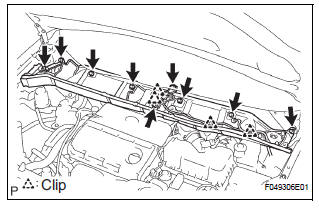
(a) Install the cowl top brace and cowl top panel subassembly outer front with the 9 bolts.
Torque: 7.5 N*m (76 kgf*cm, 66 in.*lbf) (b) Connect the wire harness to the cowl top panel subassembly outer front.
4. INSTALL WINDSHIELD WIPER MOTOR & LINK ASSEMBLY
HINT: (See page WW-3)
5. INSTALL FR WIPER ARM LH
HINT: (See page WW-3)
6. INSTALL FR WIPER ARM RH
HINT: (See page WW-3)
7. INSTALL FRONT WHEEL Torque: 103 N*m (1,050 kgf*cm, 76 ft.*lbf)
8. INSPECT AND ADJUST FRONT WHEEL ALIGNMENT
HINT: (See page SP-4)
 Reassembly
1. INSTALL SHOCK ABSORBER ASSEMBLY FRONT LH
2. INSTALL FRONT COIL SPRING INSULATOR LOWER
LH
(a) Install the front coil spring insulator lower LH onto
the shock absorber assembly front LH.
3. INST ...
 Disposal
1. DISPOSE OF SHOCK ABSORBER ASSEMBLY FRONT LH
HINT:
Dispose the RH side by the same procedures as the LH
side.
(a) Fully extend the shock absorber rod.
(b) Using a drill, make a hole in the cy ...
Other materials:
Problem symptoms table
HINT:
If a normal code is displayed during the diagnostic trouble
code check although the trouble still occurs, check the
electrical circuits for each symptom in the order given in
the charts on the following pages and proceed to the page
given for troubleshooting.
The Matrix Chart is ...
Open in Front Passenger Side Squib Circuit
DTC B0106/54 Open in Front Passenger Side Squib Circuit
DESCRIPTION
The front passenger side squib circuit consists of the center airbag sensor
assembly and the front
passenger airbag assembly.
The circuit instructs the SRS to deploy when deployment conditions are met.
DTC B0106/54 is rec ...
Navigation check mode
HINT:
This mode displays GPS satellite information.
Illustrations may differ from the actual vehicle depending
on the device settings and options. Therefore, some
detailed areas may not be shown exactly the same as on
the actual vehicle.
1. ENTER DIAGNOSTIC MODE ( )
2. NA ...
