Toyota Sienna Service Manual: Installation
1. INSTALL BRAKE VACUUM CHECK VALVE ASSEMBLY
(a) Install the brake vacuum check valve assembly and check valve grommet to the brake booster assembly.
2. INSTALL BRAKE BOOSTER GASKET
(a) Install a new brake booster gasket to the brake booster with master cylinder.
3. INSTALL BRAKE MASTER CYLINDER ASSEMBLY
(a) Install the brake booster assembly with the 4 nuts.
Torque: 13 N*m (130 kgf*cm, 9 ft.*lbf) (b) Slide the clip and connect the brake master cylinder reservoir hose to the brake master cylinder union.
(c) Slide the clip and connect the vacuum hose from the brake vacuum check valve assembly.
4. INSTALL PUSH ROD PIN
(a) Install the push rod pin to the brake booster push rod.
5. INSTALL BRAKE LINE
(a) Install the front brake tube No. 1, front brake tube No. 2, front brake tube No. 3 and front brake tube No. 4.
Torque: 15 N*m (155 kgf*cm, 11 ft.*lbf) (b) Install the rear brake tube No. 1and rear brake tube No. 2.
Torque: 15 N*m (155 kgf*cm, 11 ft.*lbf)
6. INSTALL BRAKE ACTUATOR ASSEMBLY (w/o VSC) SST 09023-00101
HINT: See page BC-184
7. INSTALL ABS & TRACTION ACTUATOR ASSEMBLY (w/ VSC) SST 09023-00101
HINT: See page BC-179.
8. INSTALL AIR CLEANER ASSEMBLY WITH HOSE
9. FILL RESERVOIR WITH BRAKE FLUID (See page BR- 3)
10. BLEED BRAKE MASTER CYLINDER (See page BR-3)
11. BLEED BRAKE LINE (See page BR-4)
12. BLEED BRAKE ACTUATOR (w/ VSC) (See page BR- 4)
13. CHECK FLUID LEVEL IN RESERVOIR (See page BR- 7)
14. CHECK BRAKE FLUID LEAKAGE
15. INSTALL INSTRUMENT PANEL SAFETY PAD INSERT SUB-ASSEMBLY NO. 1
(a) Install the instrument panel safety pad insert subassembly No. 1 with the 4 bolts.
16. INSTALL INSTRUMENT PANEL FINISH PANEL SUBASSEMBLY LOWER LH
(a) Install the instrument panel finish panel subassembly lower LH with the 2 bolts.
17. INSTALL COWL SIDE TRIM BOARD LH
(a) Install the cowl trim board plate LH with the nut.
18. INSTALL FRONT DOOR SCUFF PLATE LH
19. INSTALL COWL TOP PANEL SUB-ASSEMBLY OUTER FRONT
20. INSTALL FRONT WHEEL Torque: 103 N*m (1,050 kgf*cm, 76 ft.*lbf)
21. INSPECT BRAKE PEDAL HEIGHT (See page BR-9)
22. CHECK BRAKE ACTUATOR WITH INTELLIGENT
TESTER 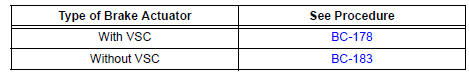
 Inspection
1. INSPECT BRAKE VACUUM CHECK VALVE ASSEMBLY
(a) Check the vacuum check valve.
(1) Slide the clip and disconnect the vacuum hose.
(2) Remove the vacuum check valve.
(3) Check that there ...
 Front brake
COMPONENTS
...
Other materials:
Antenna Coil Open / Short
DTC B2784 Antenna Coil Open / Short
DESCRIPTION
The transponder key coil is built into the transponder key amplifier and
receives a key code signal from
the transponder chip in the key. This signal is amplified by the amplifier, and
output to the transponder key
ECU.
DTC No.
...
Initialization
Items to initialize
The following items must be initialized for normal system operation
after such cases as the battery being reconnected, or maintenance
being performed on the vehicle.
Item
When to initialize
Power sliding door
(if equipped)
After reconnecting o ...
Short to B+ in Driver Side Squib Circuit
DTC B0103/12 Short to B+ in Driver Side Squib Circuit
DESCRIPTION
The driver side squib circuit consists of the center airbag sensor assembly,
the spiral cable and the
steering pad.
The circuit instructs the SRS to deploy when deployment conditions are met.
DTC B0103/12 is recorded when a ...
