Toyota Sienna Service Manual: Installation
1. INSTALL VANE PUMP ASSEMBLY
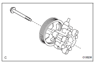
(a) Temporarily install the bolt to the vane pump assembly.
(b) Install the vane pump assembly.
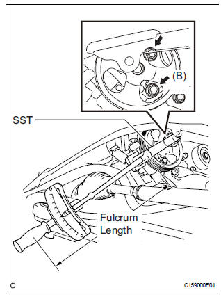
(c) Temporarily install the bolt (B).
(d) Using SST, tighten the 2 bolts.
SST 09249-63010 Torque:Without SST 43 N*m (439 kgf*cm, 32 ft.*lbf) With SST 29 N*m (294 kgf*cm, 21 ft.*lbf)
NOTICE:
- Use a torque wrench with a fulcrum length of 300 mm (11.81 in.).
- This torque value is accurate when SST is parallel to the torque wrench.
2. CONNECT POWER STEERING FLUID PRESSURE SWITCH CONNECTOR
(a) Connect the connector to the power steering fluid pressure switch.
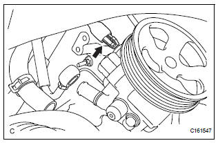
3. CONNECT PRESSURE FEED TUBE ASSEMBLY
(a) Install a new gasket to the pressure feed tube assembly.
(b) Temporarily connect the pressure feed tube assembly to the vane pump assembly with the union bolt.
(c) Fully tighten the union bolt
Torque: 50 N*m (510 kgf*cm, 37 ft.*lbf)
NOTICE: Make sure that the stopper of the pressure feed tube assembly contacts the vane pump assembly securely as shown in the illustration.
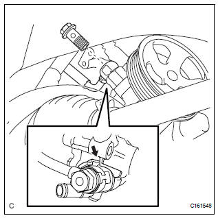
4. CONNECT NO. 1 FLUID RESERVOIR TO PUMP HOSE
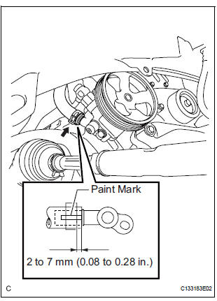
(a) Connect the No. 1 fluid reservoir to pump hose to the vane pump assembly with the clip.
NOTICE:
- Connect the No. 1 fluid reservoir to pump hose with the paint mark facing toward the rear of the vehicle.
- Push the No. 1 fluid reservoir to pump hose as far as it goes as shown in the illustration.
- Install the clip at the position specified in the illustration.
5. INSTALL FAN AND GENERATOR V BELT (See page EM-7)
6. ADD POWER STEERING FLUID
7. BLEED POWER STEERING SYSTEM (See page PS-6)
8. CHECK POWER STEERING FLUID LEVEL (See page PS-2)
9. INSPECT FOR POWER STEERING FLUID LEAK
10. INSTALL FRONT FENDER APRON SEAL RH (See page EM-62)
11. INSTALL FRONT WHEEL RH Torque: 103 N*m (1,050 kgf*cm, 76 ft.*lbf)
 Reassembly
NOTICE:
Before installation, coat the parts indicated by arrows
with power steering fluid (See page PS-7).
1. INSTALL VANE PUMP HOUSING OIL SEAL
(a) Coat a new vane pump housing oil seal lip with
...
 Rack and pinion power steering gear
COMPONENTS
...
Other materials:
Parking brake
Operating instructions
To set the parking brake, fully
depress the parking brake pedal
with your left foot while depressing
the brake pedal with your right
foot.
(Depressing the pedal again
releases the parking brake.)
Usage in winter time
NOTICEBefore driving
Fully release ...
Room Temperature Sensor Circuit
DESCRIPTION
This sensor detects the cabin temperature that is used as the basis for
temperature control and sends a
signal to the A/C amplifier.
WIRING DIAGRAM
INSPECTION PROCEDURE
1 READ VALUE OF INTELLIGENT TESTER
(a) Connect the intelligent tester to the DLC3.
(b) Turn the ignition s ...
Installation
1. INSTALL FRONT SEAT ASSEMBLY LH
Place the seat assembly in the cabin.
NOTICE:
Be careful not to damage the body.
Connect the connectors under the seat assembly.
Tighten the 2 bolts on the front side of the seat
assembly.
Torque: 37 N*m (375 kgf*cm, 27 ft.*lb ...
