Toyota Sienna Service Manual: Installation
1. INSTALL CAMSHAFT TIMING OIL CONTROL VALVE ASSEMBLY (for Bank 2 Exhaust Side)
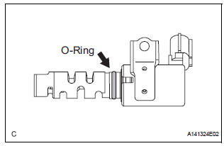
- Apply a light coat of engine oil to the new O-ring and install it to the camshaft timing oil control valve.
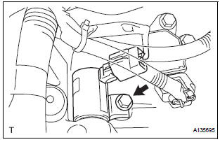
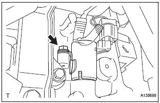
- Install the camshaft timing oil control valve
assembly with the bolt.
Torque: 10 N*m (102 kgf*cm, 7 ft.*lbf)
- Connect the camshaft timing oil control valve assembly connector
2. INSTALL CAMSHAFT TIMING OIL CONTROL VALVE ASSEMBLY (for Bank 2 Intake Side)
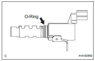
- Apply a light coat of engine oil to the new O-ring and install it to the camshaft timing oil control valve.
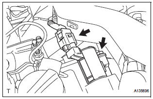
- Install the camshaft timing oil control valve
assembly with the bolt.
Torque: 10 N*m (102 kgf*cm, 7 ft.*lbf) Connect the camshaft timing oil control valve assembly connector
3. INSTALL CAMSHAFT TIMING OIL CONTROL VALVE ASSEMBLY (for Bank 1 Exhaust Side)
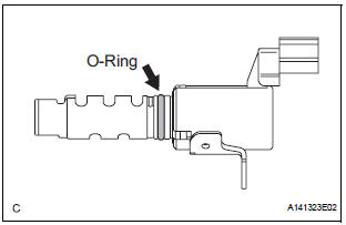
- Apply a light coat of engine oil to the new O-ring and install it to the camshaft timing oil control valve.
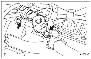
- Install the camshaft timing oil control valve
assembly with the bolt.
Torque: 10 N*m (102 kgf*cm, 7 ft.*lbf)
- Connect the camshaft timing oil control valve assembly connector
4. INSTALL CAMSHAFT TIMING OIL CONTROL VALVE ASSEMBLY (for Bank 1 Intake Side)
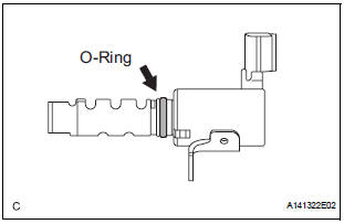
- Apply a light coat of engine oil to the new O-ring and install it to the camshaft timing oil control valve.
- Install the camshaft timing oil control valve
assembly with the bolt.
Torque: 10 N*m (102 kgf*cm, 7 ft.*lbf)
- Connect the camshaft timing oil control valve assembly connector.
5. INSTALL INTAKE AIR SURGE TANK ASSEMBLY
6. INSTALL AIR CLEANER CASE SUB-ASSEMBLY
7. INSTALL AIR CLEANER CAP SUB-ASSEMBLY
8. INSTALL NO. 1 AIR CLEANER INLET
9. INSTALL NO. 2 AIR CLEANER INLET
10. ADD ENGINE COOLANT
11. INSPECT FOR ENGINE COOLANT LEAK
12. INSPECT FOR ENGINE OIL LEAK
13. INSTALL V-BANK COVER SUB-ASSEMBLY
14. INSTALL FRONT OUTER COWL TOP PANEL SUBASSEMBLY
15. INSTALL WINDSHIELD WIPER MOTOR ASSEMBLY
 Inspection
1. INSPECT CAMSHAFT TIMING OIL CONTROL VALVE ASSEMBLY
Resistance inspection
Using an ohmmeter, measure the resistance
between the terminals.
Resistance:
6.9 to 7.9 ] ...
 Throttle body
...
Other materials:
Vehicle Speed Sensor Malfunction
DTC P0500 Vehicle Speed Sensor Malfunction
DTC P0503 Vehicle Speed Sensor "A" Intermittent / Erratic /
High
DESCRIPTION
The cruise control system uses the same vehicle speed signal that is sent to the
ECM for the SFI system.
If DTC P0500 is detected, perform the diagnosis using th ...
Display Panel does not Open, Tilt or Tilts Improperly
INSPECTION PROCEDURE
1 CHECK RADIO AND NAVIGATION ASSEMBLY
Check for foreign matter or obstructions caught in the
moving parts of the panel.
OK:
No obstruction or foreign matter found.
2 CHECK OPERATION
Check if the navigation and audio systems function
properly.
OK:
Naviga ...
Actuator Supply Voltage Circuit / Open
DESCRIPTION
The ECM monitors the output voltage to the throttle actuator. This self-check
ensures that the ECM is
functioning properly. The output voltage is usually 0 V when the ignition switch
is turned off. If the output
voltage is higher than 7 volts when the ignition switch is turned ...
