Toyota Sienna Service Manual: Installation
1. INSTALL THROTTLE BODY
(a) Install a new throttle body gasket to the intake air surge tank.
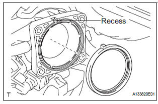
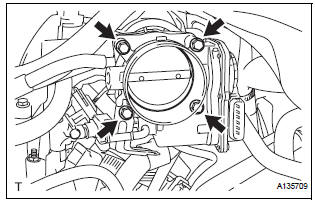
(b) Install the throttle body with the 4 bolts.
Torque: 10 N*m (102 kgf*cm, 7 ft.*lbf)
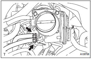
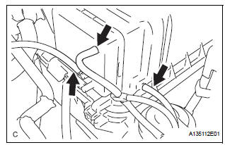
(c) Connect the 2 water by-pass hoses.
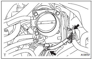
(d) Connect the throttle body connector and clamp.
2. INSTALL AIR CLEANER CASE SUB-ASSEMBLY (See page EM-59)
3. INSTALL AIR CLEANER CAP SUB-ASSEMBLY
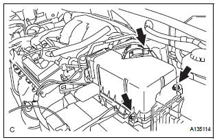
(a) Install the air cleaner cap sub-assembly with the 2 bolts.
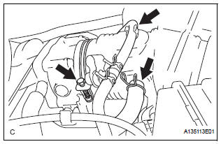
(b) Connect the the vacuum hose (EVAP) to the air cleaner hose.
(c) Install the No. 2 ventilation hose and air cleaner hose band.
(d) Connect the 3 vacuum hoses.
4. INSTALL NO. 1 AIR CLEANER INLET (See page EM- 59) 5. INSTALL NO. 2 AIR CLEANER INLET (See page EM- 60) 6. ADD ENGINE COOLANT (See page CO-7) 7. INSPECT FOR ENGINE COOLANT LEAK (See page CO-1) 8. INSTALL V-BANK COVER SUB-ASSEMBLY (See page EM-63) 9. INSTALL FRONT OUTER COWL TOP PANEL SUBASSEMBLY (See page EM-61) 10. INSTALL WINDSHIELD WIPER MOTOR ASSEMBLY
HINT: (See page WW-5)
 Removal
1. Remove windshield wiper motor assembly
hint:
(see page ww-4)
2. Remove front outer cowl top panel subassembly
(see page em-27)
3. Drain engine coolant (see page co-6)
4. Remove v-bank cover s ...
 ECM
ECM
COMPONENTS
REMOVAL
1. REMOVE GLOVE COMPARTMENT DOOR ASSEMBLY
(a) Push the right side wall and then push the left wall
to release the stoppers.
(b) Pull the glove compartment door sub-as ...
Other materials:
No Answer-Back (Hazard Warning Light and Wireless Door Lock
Buzzer)
DESCRIPTION
If there is no answer-back of the hazard light signal and the wireless door lock
buzzer although the
wireless control function is operating normally, there might be a malfunction in
the hazard light signal and
the wireless door lock buzzer signal which are output from the multiple ...
Installation
HINT:
Install the RH side by the same procedure as the LH side.
1. INSTALL REAR DISC BRAKE CYLINDER MOUNTING
LH
(a) Install the rear disc brake cylinder mounting LH with
the 2 bolts.
Torque: 88 N*m (900 kgf*cm, 65 ft.*lbf)
2. INSTALL REAR DISC BRAKE PAD SUPPORT PLATE
(a) Install the rear d ...
Power Source Circuit
DESCRIPTION
This is the power source circuit for the outer mirror control ECU.
WIRING DIAGRAM
INSPECTION PROCEDURE
1 INSPECT OUTER MIRROR CONTROL ECU (POWER SOURCE)
Disconnect the O9 or O11 ECU connector.
Measure the voltage and resistance according to the
value(s) in the t ...
