Toyota Sienna Service Manual: Installation
1. INSTALL FUEL INJECTOR ASSEMBLY
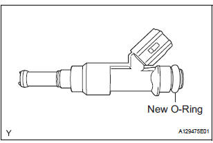
(a) Apply a light coat of spindle oil or gasoline to new Orings, and install them to each injector.
(b) Apply a light coat of spindle oil or gasoline where the fuel delivery pipe contacts the O-ring.
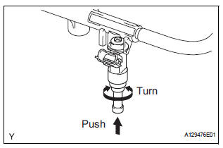
(c) Push the fuel injector while turning it to install the injector in the fuel delivery pipe.
(d) Position the fuel injector connector outward.
NOTICE:
|
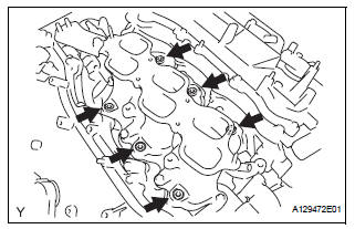
(e) Install 6 new insulators to the intake manifold.
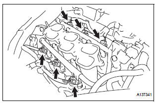
(f) Place the fuel delivery pipe which has the 6 fuel injectors installed to it in position on the intake manifold.
| NOTICE: Be careful not to drop the fuel injectors when installing the fuel delivery pipe. |
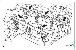
(g) Temporarily install the 5 bolts which are used to hold the fuel delivery pipe to the intake manifold.
| NOTICE: After installing the fuel injectors, check that they turn smoothly. If not, reinstall the injectors with new O-rings. |
(h) Tighten the 5 bolts which are used to hold the fuel delivery pipe to the intake manifold.
Torque: 21 N*m (214 kgf*cm, 15 ft.*lbf)
(i) Connect the 6 fuel injector connectors.
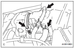
2. CONNECT FUEL TUBE SUB-ASSEMBLY
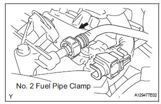
(a) Push in the tube connector onto the pipe until the tube connector makes a "click" sound.
NOTICE:
|
(b) Install the No. 2 fuel pipe clamp.
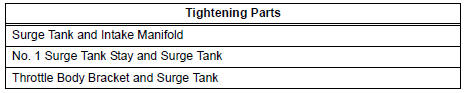
3. INSTALL INTAKE AIR SURGE TANK ASSEMBLY
NOTICE:
DO NOT apply oil to the bolts listed below:
 |
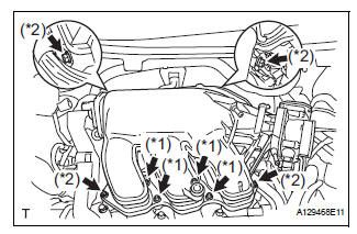
(a) Install a new gasket to the intake air surge tank assembly.
(b) Using a 5 mm hexagon socket wrench, install the 4 bolts. (*1) Torque: 18 N*m (184 kgf*cm, 13 ft.*lbf) (c) Install the intake air surge tank assembly with the 2 nuts and 2 bolts. (*2)
Torque: Nut 16 N*m (163 kgf*cm, 12 ft.*lbf) Bolt 21 N*m (214 kgf*cm, 15 ft.*lbf)
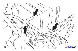
(d) Connect the connector.
(e) Connect the union to check valve hose. (*1) (f) Connect the No. 1 ventilation hose. (*2)
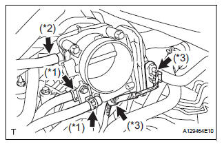
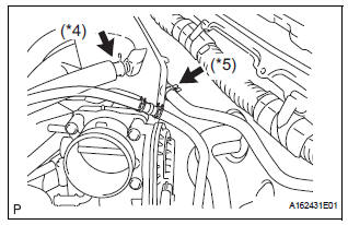
(g) Install the clamp and connect the throttle with motor body assembly connector. (*3) (h) Connect the vapor feed hose assembly. (*4) (i) Connect the 2 water by-pass hoses to the throttle with motor body assembly. (*5)
4. INSTALL AIR CLEANER CAP SUB-ASSEMBLY
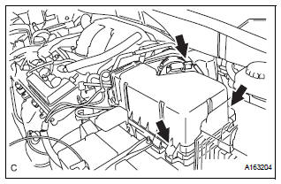
(a) Install the 2 bolts and air cleaner cap sub-assembly.
(b) Connect the No. 2 ventilation hose and air cleaner hose band.
(c) Connect the vacuum hose (EVAP) to the air cleaner hose.
(d) Connect the 3 vacuum hoses.
5. ADD ENGINE COOLANT (See page CO-7)
6. CONNECT CABLE TO NEGATIVE BATTERY TERMINAL 7. INSPECT FOR ENGINE COOLANT LEAK (See page CO-1) 8. INSTALL NO. 1 ENGINE UNDER COVER 9. INSPECT FOR FUEL LEAK (See page FU-7)
10. INSTALL V-BANK COVER SUB-ASSEMBLY (See page EM-63) 11. INSTALL COWL TOP PANEL SUB-ASSEMBLY OUTER FRONT
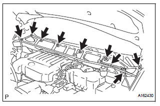
(a) Install the 7 bolts and the cowl top panel subassembly outer front.
Torque: 7.5 N*m (76 kgf*cm, 66 in.*lbf) (b) Connect the fuel pump resistor connector.
(c) Connect the wire harness clamp.
12. INSTALL NO. 1 COWL TOP TO COWL BRACE INNER

(a) Install the 2 bolts and the No.1 cowl top to cowl brace inner.
Torque: 7.5 N*m (76 kgf*cm, 66 in.*lbf)
13. INSTALL WINDSHIELD WIPER MOTOR AND LINK ASSEMBLY (See page WW-6) 14. INSTALL FRONT WIPER ARM LH (See page WW-6) 15. INSTALL FRONT WIPER ARM RH (See page WW-7)
 Inspection
1. INSPECT FUEL INJECTOR ASSEMBLYV
(A) inspect the injector resistance.
(1) Using an ohmmeter, measure the resistance
between the terminals.
Standard resistance
If the resistance is not a ...

Other materials:
Installation
1. INSTALL BACK DOOR GLASS
Clean and shape the contact surface of the vehicle
body.
Using a knife, cut away any rough adhesive on
the contact surface of the body to ensure the
appropriate surface shape.
HINT:
Leave as much adhesive on the body as
possible.
& ...
Fuel tank
Components
REMOVAL
1. DISCHARGE FUEL SYSTEM PRESSURE
(See page FU-1)
2. REMOVE CHARCOAL CANISTER PROTECTOR (See
page FU-30)
3. REMOVE REAR FLOOR NO. 2 CROSSMEMBER BRACE LH
(a) Remove the 2 bolts and the rear floor No. 2
crossmember brace LH.
4. REMOVE FUEL TANK FILLER HOSE COVER ...
Removal
HINT:
Use the same procedures for the RH side and LH side.
The procedures listed below are for the LH side.
1. PRECAUTION
CAUTION: Be sure to read "PRECAUTION" thoroughly before
servicing.
2. DISCONNECT CABLE FROM NEGATIVE BATTERY
TERMINAL
NOTICE:
Wait for 90 seconds ...
