Toyota Sienna Service Manual: Installation
1. Install air fuel ratio sensor (for bank 2 sensor 1)
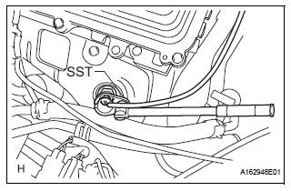
(a) Using SST, install the sensor to the exhaust manifold LH.
SST 09224-00010
Torque: 40 N*m (408 kgf*cm, 30 ft.*lbf) for use with SST 44 N*m (449 kgf*cm, 32 ft.*lbf) for use without SST
HINT:
- Use a torque wrench with a fulcrum length of 30 cm (11.81 in.).
- Make sure that SST and a wrench are connected in a straight line.
(b) Connect the sensor connector
2. INSTALL AIR FUEL RATIO SENSOR (for Bank 1 Sensor 1)
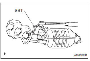
(a) Using SST, install the sensor to the exhaust manifold RH.
SST 09224-00010
Torque: 40 N*m (408 kgf*cm, 30 ft.*lbf) for use with SST
44 N*m (449 kgf*cm, 32 ft.*lbf) for use without SST
HINT:
- Use a torque wrench with a fulcrum length of 30 cm (11.81 in.).
- Make sure that SST and wrench are connected in a straight line.
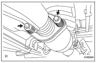
3. INSTALL EXHAUST MANIFOLD RH
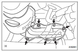
(a) Install the exhaust manifold RH with a new gasket and 6 nuts.
Torque: 21 N*m (214 kgf*cm, 15 ft.*lbf)
(b) Install the exhaust manifold stay with the nut and bolt.
Torque: 35 N*m (357 kgf*cm, 26 ft.*lbf) (c) Connect the air fuel ratio sensor (for Bank 1 Sensor 2) connector.
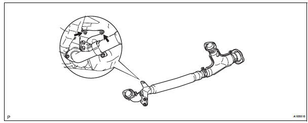
4. INSTALL FRONT EXHAUST PIPE ASSEMBLY
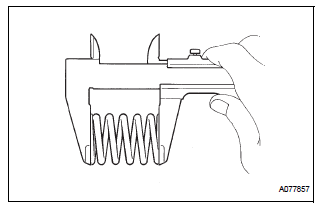
(a) Check compression springs.
(1) Check the compression springs using vernier calipers.
Specified length: 38.86 mm (1.5299 in.)
HINT:
If the result is not as specified, replace the compression spring.
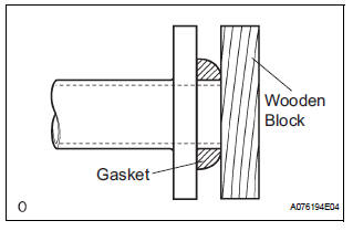
(b) Install the gasket.
(1) Install a new gasket by hand onto the front exhaust pipe assembly.
(2) Using a plastic hammer and wooden block, tap in the new gasket until its surface is flush with the front exhaust pipe.
NOTICE:
|
(c) Install 2 new gaskets to the front exhaust pipe assembly.
(d) Install the front exhaust pipe assembly with the 4 nuts.
Torque: 62 N*m (632 kgf*cm, 46 ft.*lbf)
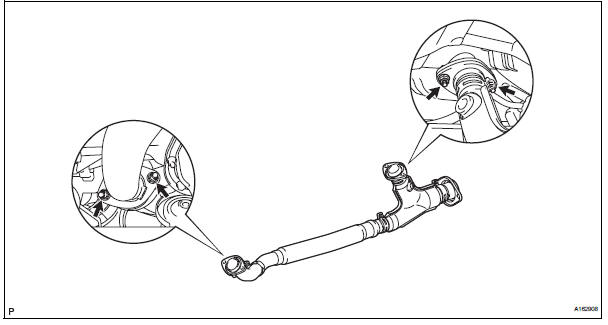
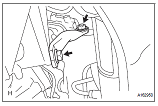
(e) Install the center exhaust pipe assembly with the 2 compression springs and 2 bolts.
Torque: 43 N*m (438 kgf*cm, 32 ft.*lbf) (f) Install the No. 1 exhaust pipe support bracket with the 2 new nuts.
Torque: 21 N*m (214 kgf*cm, 15 ft.*lbf)
(g) Connect the heated oxygen sensor (for Bank 1 sensor 2) connector
5. CONNECT CABLE TO NEGATIVE BATTERY TERMINAL
6. INSPECT FOR EXHAUST GAS LEAK
 Inspection
1. INSPECT AIR FUEL RATIO SENSOR
(a) Measure the resistance of the sensor.
Standard resistance
If the resistance is not as specified, replace the
sensor. ...
 Air fuel ratio sensor (for 4wd)
Components
...
Other materials:
Diagnostic trouble code chart
1. DTC CHECK
If a malfunction code is displayed during the DTC check ,
check the suspected area listed for that code in the table
below, and proceed to the appropriate page.
DIAGNOSTIC TROUBLE CODE CHART
DTC No.
Detection Item
Suspect Area
B1244
Light Se ...
Towing with a wheel-lift type truck
From the front (2WD models)
Release the parking brake.
From the front (AWD models)
Use a towing dolly under the rear
wheels.
From the rear
Use a towing dolly under the front
wheels. ...
Inspection
1. INSPECT STEERING PAD SWITCH LH (w/o
Navigation System)
Measure the resistance according to the values in
the table below.
Standard resistan
If the result is not as specified, replace the steering
pad switch LH.
2. INSPECT STEERING PAD SWITCH RH (w/ Navigation
System)
...
