Toyota Sienna Service Manual: Installation
1. INSTALL HEATED OXYGEN SENSOR (for Bank 2 Sensor 2)
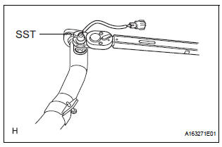
(a) Using SST, install the heated oxygen sensor to the front exhaust pipe.
SST 09224-00010
Torque: 40 N*m (408 kgf*cm, 30 ft.*lbf) for use with SST
44 N*m (449 kgf*cm, 32 ft.*lbf) for use without SST
HINT:
- Use a torque wrench with a fulcrum length of 30 cm (11.81 in.).
- Make sure that SST and a wrench are connected in a straight line.
2. INSTALL FRONT EXHAUST PIPE ASSEMBLY
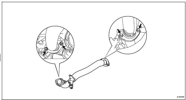
(a) Install 2 new gaskets to the front exhaust pipe assembly.
(b) Install the front exhaust pipe assembly with the 2 bolts and 2 nuts.
Torque: Bolt 43 N*m (440 kgf*cm, 32 ft.*lbf)
Nut 62 N*m (632 kgf*cm, 46 ft.*lbf)
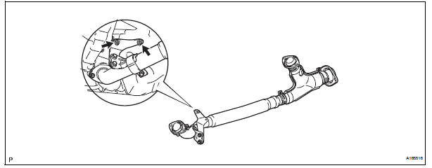
(c) Install the No. 1 exhaust pipe support bracket with 2 new nuts.
Torque: 21 N*m (214 kgf*cm, 15 ft.*lbf)
(d) Connect the heated oxygen sensor (for Bank 2 sensor 2) connector.
3. INSTALL HEATED OXYGEN SENSOR (for Bank 1 Sensor 2)
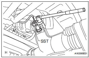
(a) Using SST, install the heated oxygen sensor.
SST 09224-00010
Torque: 40 N*m (408 kgf*cm, 30 ft.*lbf) for use with SST 44 N*m (449 kgf*cm, 32 ft.*lbf) for use without SST
(b) Connect the heated oxygen sensor (for Bank 1 Sensor 2) connector.
HINT:
- Use a torque wrench with a fulcrum length of 30 cm (11.81 in.).
- Make sure that SST and a wrench are connected in a straight line.
4. CONNECT CABLE TO NEGATIVE BATTERY TERMINAL
5. INSPECT FOR EXHAUST GAS LEAK
 Inspection
1. Inspect heated oxygen sensor (for bank 1
sensor 2)
(a) Measure the resistance of the sensor.
Standard resistance
If the resistance is not as specified, replace the
sensor.
2. HEATED OXY ...
 Fuel tank cap
Inspection
1. Inspect fuel tank cap assembly
(A) visually check that the cap and gasket are not
deformed or damaged.
If the result is not as specified, replace the cap
assembly or gasket. ...
Other materials:
How to proceed with
troubleshooting
HINT:
Troubleshoot in accordance with the procedures on the
following pages.
1 VEHICLE BROUGHT TO WORKSHOP
2 CUSTOMER PROBLEM ANALYSIS CHECK AND SYMPTOM CHECK
3 INSPECT COMMUNICATION FUNCTION OF LARGE-SCALE MULTIPLEX
COMMUNICATION SYSTEM (BEAN)
Use the intelligent tester to check for norma ...
Engine Coolant Temperature Circuit Range /
Performance Problem
DTC P0116 Engine Coolant Temperature Circuit Range /
Performance Problem
DESCRIPTION
Refer to DTC P0115
DTC No.
DTC Detection Condition
Trouble Area
P0116
ECTs as listed below are nearly same (2 trip detection
logic):
ECT when engine is start ...
Personal/interior
lights
Front
Turns the light on/off
Rear
Turns the light on/off
When the personal/interior light main switch is in the off position, the
rear personal lights will not turn on even if the switch is on.
Type A
Type B
...
