Toyota Sienna Service Manual: Installation
1. Connect inlet sub-assembly
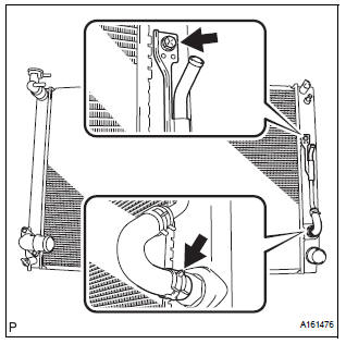
(a) Connect the inlet hose to the radiator.
(b) Install the inlet sub-assembly to the radiator with the bolt.
Torque: 7.1 N*m (72 kgf*cm, 63 in.*lbf)V
2. Install no. 2 Radiator support
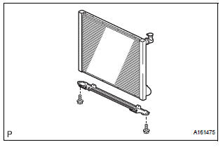
(A) install the no. 2 Radiator support to the radiator with the 2 bolts.
Torque: 12.7 N*m (130 kgf*cm, 112 in.*Lbf)
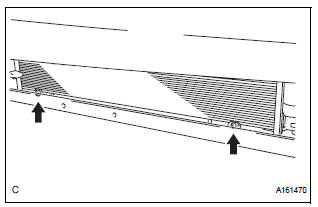
3. INSTALL RADIATOR SUPPORT LOWER
(a) Install the 2 radiator support lowers to the radiator.
4. INSTALL FAN SHROUD WITH FAN MOTOR
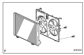
(a) Install the fan shroud with fan motor to the radiator with the 2 bolts.
Torque: 6 N*m (61 kgf*cm, 4 ft.*lbf)
5. INSTALL RADIATOR ASSEMBLY WITH FAN SHROUD AND FAN MOTOR
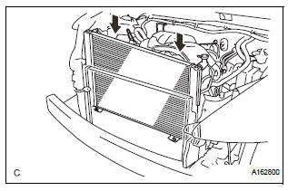
(a) Install the radiator assembly with fan shroud and fan motor.
(b) Install the condenser assembly to the radiator assembly with fan shroud and fan motor with the 2 bolts.
Torque: 3.9 N*m (40 kgf*cm, 35 in.*lbf)
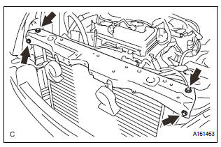
6. INSTALL NO. 1 RADIATOR SUPPORT
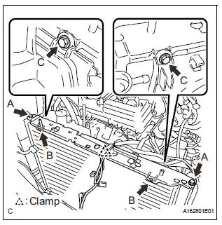
(a) Install the No. 1 radiator support to the radiator assembly with the 6 bolts.
Torque: Bolt A 13 N*m (130 kgf*cm, 9 ft.*lbf)
Bolt B 3.9 N*m (40 kgf*cm, 35 in.*lbf)
Bolt C 6 N*m (61 kgf*cm, 4 ft.*lbf)
(b) Attach the clamp.
7. INSTALL RADIATOR SUPPORT CUSHION
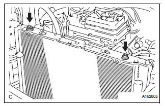
(a) Install the 2 radiator support cushions to the No. 1 radiator support.
8. INSTALL PRESSURE FEED TUBE ASSEMBLY
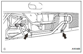
(a) Install the 2 bolts.
Torque: 7.8 N*m (80 kgf*cm, 69 in.*lbf)
9. INSTALL HEADLIGHT BRACKET RH
(a) Install the headlight bracket RH with the 3 nuts.
10. INSTALL RADIATOR SIDE DEFLECTOR RH
(a) Engage the 3 claws to install the radiator side deflector RH.
11. INSTALL HEADLIGHT ASSEMBLY RH
(a) The installation procedure of the RH side is the same as the LH side.
HINT: See page LI-78
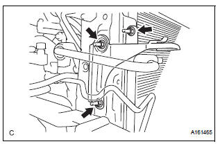
12. CONNECT NO. 2 OIL COOLER OUTLET TUBE SUBASSEMBLY
(a) Install the No. 2 oil cooler outlet tube sub-assembly with the 2 bolts.
Torque: 6 N*m (61 kgf*cm, 4 ft.*lbf)
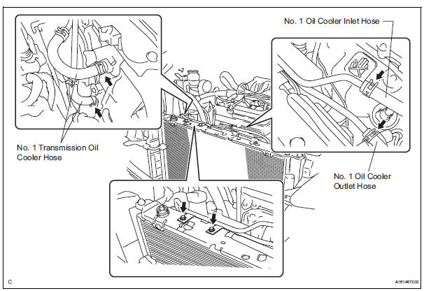
(b) Connect the No. 1 transmission oil cooler hoses to the radiator.
(c) Connect the No. 1 oil cooler inlet and No. 1 oil cooler outlet hoses to the No. 2 oil cooler outlet tube sub-assembly.
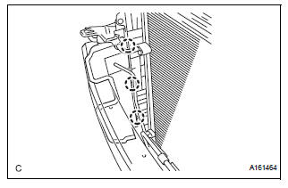
13. INSTALL RADIATOR UPPER SUPPORT SUBASSEMBLY
(a) Install the radiator upper support sub-assembly with the 4 bolts.
Torque: 5.0 N*m (51 kgf*cm, 44 in.*lbf)
14. CONNECT COOLING FAN ECU CONNECTOR
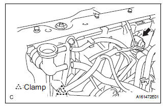
(a) Connect the connector.
(b) Attach the clamp.
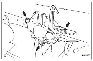
15. INSTALL HOOD LOCK SUPPORT SUB-ASSEMBLY
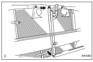
(a) Install the hood lock support sub-assembly with the 2 bolts.
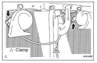
(b) Attach the clamp.
(c) Connect the low pitched horn and high pitched horn connectors.
(d) Connect the ambient temperature sensor connector.
16. INSTALL HOOD LOCK ASSEMBLY
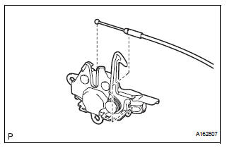
(a) Connect the cable to the hood lock assembly.
(b) Install the hood lock assembly with the 3 bolts.
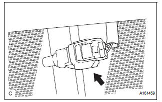
Torque: 8 N*m (82 kgf*cm, 6 ft.*lbf) (c) With Hood Courtesy Switch: (1) Connect the connector.
17. INSTALL HOOD LOCK RELEASE LEVER PROTECTOR
(a) Engage the 4 claws to install the hood lock release lever protector.
18. CONNECT NO. 2 RADIATOR HOSE
(a) Connect the No. 2 radiator hose to the radiator.
19. CONNECT NO. 1 RADIATOR HOSE
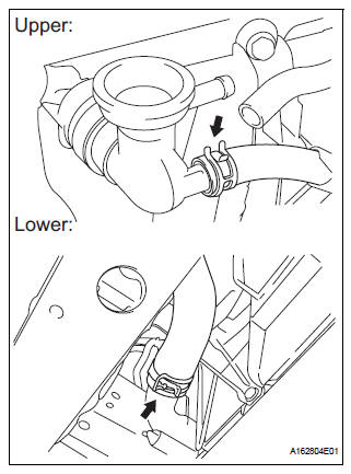
(a) Connect the No. 1 radiator hose to the radiator.
20. CONNECT RADIATOR RESERVE TANK HOSE OR PIPE
(a) Connect the radiator reserve tank hose or pipe to the radiator.
21. INSTALL NO. 1 AIR CLEANER INLET (See page EM- 59)
22. INSTALL FRONT BUMPER ENERGY ABSORBER
23. INSTALL FRONT BUMPER ASSEMBLY (See page ET- 9)
24. INSTALL BATTERY (See page EM-59)
25. INSTALL NO. 2 AIR CLEANER INLET (See page EM- 60)
26. ADD ENGINE COOLANT (See page CO-7)
27. INSPECT FOR COOLANT LEAK (See page CO-1)
28. ADD AUTOMATIC TRANSAXLE FLUID
29. CHECK AUTOMATIC TRANSAXLE FLUID (See page AX-123)
30. INSTALL NO. 1 ENGINE UNDER COVER (See page EM-63)
31. INSTALL V-BANK COVER SUB-ASSEMBLY (See page EM-63)
32. VEHICLE PREPARATION FOR HEADLIGHT AIM ADJUSTMENT (See page LI-71)
33. PREPARATION FOR HEADLIGHT AIMING (Using a tester) (See page LI-71)
34. PREPARATION FOR HEADLIGHT AIMING (Using a screen) (See page LI-72)
35. HEADLIGHT AIMING INSPECTION (See page LI-74)
36. HEADLIGHT AIMING ADJUSTMENT (See page LI-75)
37. VEHICLE PREPARATION FOR FOG LIGHT AIM ADJUSTMENT (w/ Fog Light) (See page LI-82)
38. PREPARATION FOR FOG LIGHT AIMING (Using a screen) (w/ Fog Light) (See page LI-83)
39. FOG LIGHT AIMING INSPECTION (w/ Fog Light) (See page LI-84)
40. FOG LIGHT AIMING ADJUSTMENT (w/ Fog Light) (See page LI-85)
 Reassembly
1. Install lower radiator tank
(a) After checking that there are no foreign objects in
the lock plate groove, install a new O-ring without
twisting it.
HINT:
When cleaning the lock plate groo ...

Other materials:
Position Sensor Circuit
DESCRIPTION
When SET and 1 or 2 are pressed, the position sensor detects the mirror
position and sends the signal to
the outer mirror control ECU. Then when position 1 or 2 is pressed, the outer
mirror control ECU drives
the mirror motor based on the memorized sensor positions.
HINT:
The ...
Oxygen (A/F) Sensor Pumping Current Circuit
HINT:
Although the DTC titles say oxygen sensor, these DTCs relate to the
Air-Fuel Ratio (A/F) sensor.
Sensor 1 refers to the sensor mounted in front of the Three-Way
Catalytic Converter (TWC) and
located near the engine assembly.
DESCRIPTION
Refer to DTC P2195 (See page ES-355 ...
Wrong Disc/ Disc cannot be Read
DTC 44-41 Wrong Disc
DTC 44-42 Disc cannot be Read
DESCRIPTION
DTC No.
DTC Detecting Condition
Trouble Area
44-41
An unsuitable disc is inserted
DVD
Television display assembly
44-42
The disc cannot be read.
IN ...
