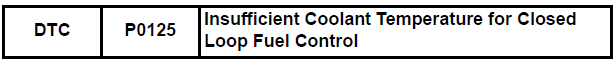
Toyota Sienna Service Manual: Insufficient Coolant Temperature for Closed Loop Fuel Control
DESCRIPTION
Refer to DTC P0115 (See page ES-133).
MONITOR DESCRIPTION
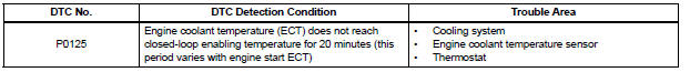
The resistance of the ECT sensor varies in proportion to the actual ECT. The ECM supplies a constant voltage to the sensor and monitors the signal output voltage of the sensor. The signal voltage output varies according to the changing resistance of the sensor. After the engine is started, the ECT is monitored through this signal. If the ECT sensor indicates that the engine is not yet warm enough for closed-loop fuel control, despite a specified period of time having elapsed since the engine was started, the ECM interprets this as a malfunction in the sensor or cooling system and sets the DTC.
Example: The ECT is 0°C (32°F) at engine start. After 5 minutes running time, the ECT sensor still indicates that the engine is not warm enough to begin closed-loop fuel (air-fuel ratio feedback) control. The ECM interprets this as a malfunction in the sensor or cooling system and sets the DTC.
MONITOR STRATEGY
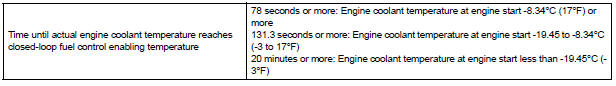
TYPICAL ENABLING CONDITIONS
TYPICAL MALFUNCTION THRESHOLDS
WIRING DIAGRAM
Refer to DTC P0115 (See page ES-134).
INSPECTION PROCEDURE
HINT
- If any of DTCs P0115, P0116, P0117 or P0118 are set simultaneously with DTC P0125, the Engine Coolant Temperature (ECT) sensor may have an open or a short circuit. Troubleshoot those DTCs first.
- Read freeze frame data using the intelligent tester. The ECM records vehicle and driving condition information as freeze frame data the moment a DTC is stored. When troubleshooting, freeze frame data can be helpful in determining whether the vehicle was running or stopped, whether the engine was warmed up or not, whether the air-fuel ratio was lean or rich, as well as other data recorded at the time of a malfunction.
1 CHECK ANY OTHER DTCS OUTPUT (IN ADDITION TO DTC P0125)
(a) Connect the intelligent tester to the DLC3.
(b) Turn the ignition switch to the ON position.
(c) Turn the tester on.
(d) Select the following menu items: DIAGNOSIS / ENHANCED OBD II / DTC INFO / CURRENT CODES.
(e) Read the DTCs.
Result 
HINT:
If any DTCs other than P0125 are output, troubleshoot those DTCs first.


2 INSPECT THERMOSTAT
(a) Remove the thermostat (See page CO-16).
(b) Check the valve opening temperature of the thermostat (See page CO-17).
Standard: 80 to 84°C (176 to 183°F)
HINT:
In addition to the above check, confirm that the valve is completely closed when the temperature is below the standard.
(c) Reinstall the thermostat (See page CO-17).


3 CHECK COOLING SYSTEM
(a) Check for defects in the cooling system that might cause the system to be too cold, such as abnormal radiator fan operation or any modifications.

REPLACE ENGINE COOLANT TEMPERATURE SENSOR (See page ES-516)
 Throttle / Pedal Position Sensor / Switch "A" Circuit Range / Performance
Problem
Throttle / Pedal Position Sensor / Switch "A" Circuit Range / Performance
Problem
HINT:
This DTC relates to the Throttle Position (TP) sensor.
DESCRIPTION
Refer to DTC P0120 (See page ES-145).
MONITOR DESCRIPTION
The ECM uses the TP sensor to monitor the throttle valve ...
 Coolant Thermostat (Coolant Temperature Below Thermostat Regulating
Temperature)
Coolant Thermostat (Coolant Temperature Below Thermostat Regulating
Temperature)
HINT:
This DTC relates to the thermostat.
DESCRIPTION
This DTC is set when the Engine Coolant Temperature (ECT) does not reach 75°C
(167°F) despite
sufficient engine warm-up time.
MON ...
Other materials:
Terminals of ECU
1. FOLD SEAT CONTROL ECU LH
Disconnect the fold seat control ECU connectors.
Measure the voltage and resistance of the wire
harness side connectors.
If the result is not as specified, there may be a
malfunction on the wire harness side.
Reconnect the fold seat control E ...
ECM Power Source Circuit
DESCRIPTION
When the ignition switch is turned to the ON position, the battery voltage is
applied to terminal IGSW of
the ECM. The ECM MREL output signal causes a current to flow to the coil,
closing the contacts of the EFI
relay and supplying power to terminal +B of the ECM.
If the igniti ...
Fail-safe chart
If any of the following DTCs are set, the ECM enters fail-safe
mode to allow the vehicle to be driven temporarily.
HINT:
*1: The vehicle can be driven slowly when the accelerator
pedal is depressed firmly and slowly. If the accelerator
pedal is depressed quickly, the vehicle may ...
