Toyota Sienna Service Manual: Jam Protection Function Activates During Power Slide Door RH Operation
DESCRIPTION
- It may be caused by ill-fitting slide door, faulty touch sensor or faulty pulse sensor.
- The power slide door ECU activates the slide motor to open / close the power slide door, thus controlling the power slide door operation. For jam and foreign object detection, the power slide door system uses the pulse sensor built into the slide motor and the touch sensor installed in the front side of the slide door.
- When the touch sensor comes in contact with an object while the slide door is closing, the resistance of the touch sensor changes, which is monitored by the power slide door ECU. If a change in resistance is detected, the ECU will judge it to be a jam and foreign object detection in the direction that the power slide door is moving and reverse slide motor rotation. The touch sensor operates only while the slide door is closing. It does not operate while the slide door is opening.
- The pulse sensor detects changes in the operating speed of the slide door while the slide door is operating. When the sensor detects a change in the operating speed, the pulse from the sensor also changes, which is monitored by the power slide door ECU. If there is a pulse change detected, the ECU will judge it to be a jam and foreign object detection in the direction that the power slide door is moving and reverse slide motor rotation.
- If a jam and foreign object detection by the touch sensor and the pulse sensor has occurred 2 or more consecutive times and if the 2nd or most recent detection has occurred during closing, then the power slide door ECU will cancel automated slide door operation and switch the slide door to manual operation mode (not electrically controlled). In order to return the power slide door system to normal operation mode, perform either of the following: manually close the slide door fully or press the satellite switch for the power slide door or the power slide door control switch again (reset operation).
WIRING DIAGRAM
INSPECTION PROCEDURE
1 CHECK DTC
- Check for DTC B2223. DTC B2223 indicates a pulse sensor malfunction.
- Without code outputs, proceed to A.
- With code outputs, proceed to B.
2 VISUALLY CHECK
- Check for foreign objects on the sliding area.
3 MANUAL OPERATION
- Turn OFF* the power slide door main switch in order to
locate the area where reverse operation has been
triggered.
* OFF is a condition that orange paint on the top of the switch does not appear.
- Move the slide door manually, and check to make sure no obstacles are present (no extra resistance) around the reverse operation area and that the slide door smoothly operates.
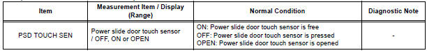
4 READ VALUE OF INTELLIGENT TESTER
- Using the intelligent tester, check the DATA LIST for proper functioning of power slide door touch sensor RH.
OK (Power slide door ECU RH):
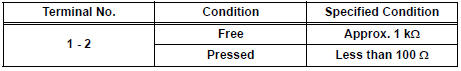
5 INSPECT POWER SLIDE DOOR TOUCH SENSOR RH
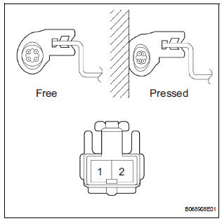
- Inspect the resistance of the sensor.
Resistance
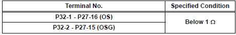
6 CHECK WIRE HARNESS (POWER SLIDE DOOR TOUCH SENSOR RH - POWER SLIDE DOOR ECU RH)
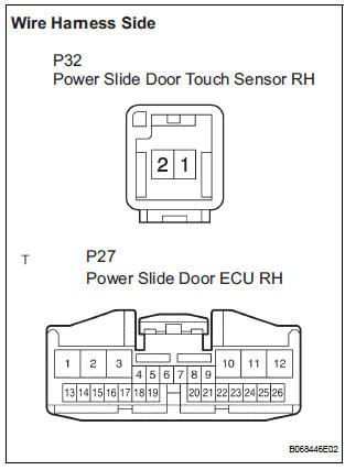
- Disconnect the P32 sensor and the P27 ECU connectors.
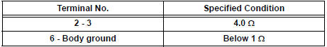
- Check the resistance between the wire harness side connectors.
Resistance (Check for open circuit)
REPLACE POWER SLIDE DOOR ECU RH
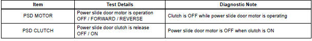
7 PERFORM ACTIVE TEST BY INTELLIGENT TESTER
- Select the ACTIVE TEST and then check that the power slide door control motor and clutch RH operates.
HINT: During the ACTIVE TEST, the intelligent tester sends a signal to the power slide door ECU RH to drive the motor and clutch. If the motor and clutch operates, the motor and clutch itself and the wire harness between the motor and clutch and the power slide door ECU are considered to be functioning normally.
OK (Power slide door ECU RH):
8 INSPECT SLIDE DOOR CONTROL MOTOR AND CLUTCH ASSEMBLY RH
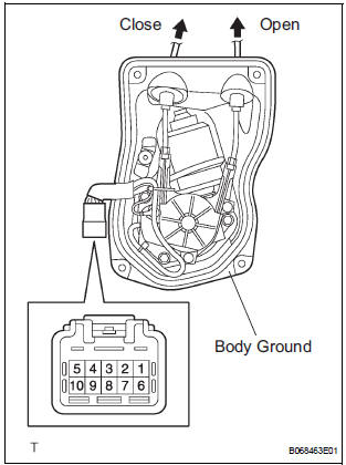
- Remove the motor and clutch.
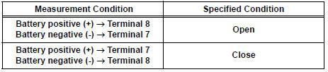
- Connect the battery positive (+) lead to terminal 3 and battery negative (-) terminal lead to terminal 2.
- Apply battery voltage to the terminals and check the motor operation.
OK
- Check the resistance of the clutch terminals.
Resistance
- Reinstall the motor and clutch with the connector connected.
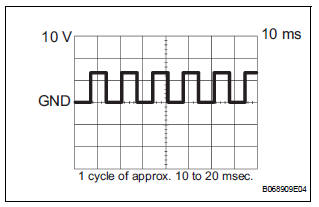
- Check the pulse of the pulse sensor.
- Using an oscilloscope, check the pulse generated when the door is manually opened and closed.
Reference
HINT: A cycle of the pulse changes between approx. 10 to 20 msec. according to the speeds that the slide door is moving.
NOTICE: When disconnecting the control motor and clutch, initialize the power slide door system
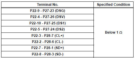
9 CHECK WIRE HARNESS (SLIDE DOOR CONTROL MOTOR AND CLUTCH - POWER SLIDE DOOR ECU)
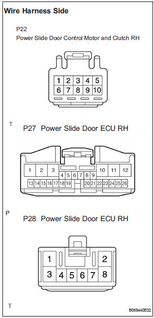
- Disconnect the P22 motor and clutch, the P27 and P28 ECU connectors.
- Check the resistance between the wire harness side connectors.
Resistance (Check for open circuit)
REPLACE POWER SLIDE DOOR ECU RH
 Jam Protection Function Activates During Power Slide Door LH
Operation
Jam Protection Function Activates During Power Slide Door LH
Operation
DESCRIPTION
It may be caused by ill-fitting slide door, faulty touch sensor or
faulty pulse sensor.
The power slide door ECU activates the slide motor to open / close
the power ...
 Power Slide Door does not Fully Open
DESCRIPTION
When the LH / RH rear window is open 105 mm (5.91 in.) or more,
the slide door half-open stopper is
activated to force the slide door to stop at approximately 105 mm (5.91 i ...
Other materials:
Low Battery Positive Voltage
DTC C1241/41 Low Battery Positive Voltage
DESCRIPTION
WIRING DIAGRAM
INSPECTION PROCEDURE
1 INSPECT ECU-IG FUSE
(a) Remove the ECU-IG fuse from the driver side J/B.
(b) Check continuity of the ECU-IG fuse.
Standard resistance
2 CHECK BATTERY
(a) Check the positive battery volt ...
Diagnosis system
1. BUS CHECK
Select "BUS CHECK" from the "OBD/MOBD
MENU" screen.
HINT:
The ECUs and sensors that are properly connected
to the CAN communication system can be displayed
using the intelligent tester via the CAN VIM.
Press "ENTER" on the intelligent te ...
Removal
1. Remove rear wheel
2. Remove exhaust pipe assembly
Hint:
(see page ex-8)
3. Remove propeller with center bearing
shaft assembly
Hint:
(see page pr-3)
4. REMOVE REAR DIFFERENTIAL FILLER PLUG
(A) using a hexagon wrench (10 mm), remove the filler
plug and gasket.
5. Remove rear differentia ...
