Toyota Sienna Service Manual: Key Lock-in Prevention Function does not Work Properly (Manual Operation and Operation Interlocked with Key are Active)
DESCRIPTION
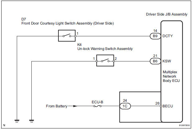
The un-lock warning switch turns ON when the key is inserted in the ignition key cylinder. The courtesy light switch turns ON when the driver side door is opened. These 2 switches are monitored by the body ECU.
In order to prevent the key from being locked in, the body ECU controls door locking operation according to the conditions of these switches so that the doors are not locked.
WIRING DIAGRAM
INSPECTION PROCEDURE
1 INSPECT FUSE (ECU-B)
- Remove ECU-B fuse from engine room junction block.
- Measure the resistance.
Standard resistance: Below 1 Ω
2 READ VALUE OF DATA LIST
- Using the intelligent tester, check that the un-lock warning switch signal is output when the switch is operated.
BODY (Multiplex network body ECU)

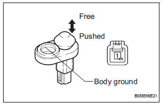
3 INSPECT UN-LOCK WARNING SWITCH ASSEMBLY
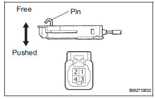
- Remove the un-lock warning switch.
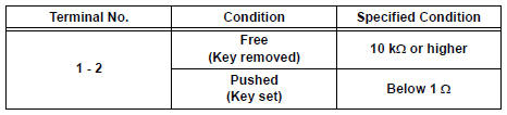
- Measure the resistance according to the value(s) in the table below.
Standard resistance
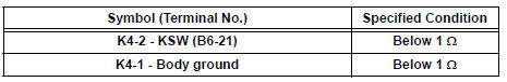
4 CHECK HARNESS AND CONNECTOR (UN-LOCK WARNING SWITCH ASSEMBLY - DRIVER SIDE J/B)
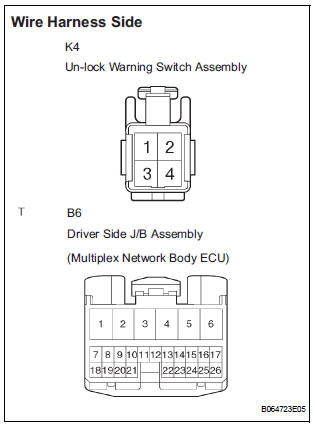
- Disconnect the K4 switch and B6 body ECU connectors.
- Measure the resistance according to the value(s) in the table below.
Standard resistance
REPLACE DRIVER SIDE JUNCTION BLOCK ASSEMBLY (MULTIPLEX NETWORK BODY ECU)
5 READ VALUE OF DATA LIST
- Using the intelligent tester, check that the driver side door courtesy light switch signal s output when the switch is operated.
BODY (Multiplex network body ECU)

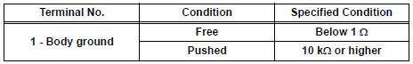
6 INSPECT FRONT DOOR COURTESY LIGHT SWITCH ASSEMBLY (DRIVER SIDE)
- Remove the courtesy light switch.
- Measure the resistance according to the value(s) in the table below.
Standard resistance
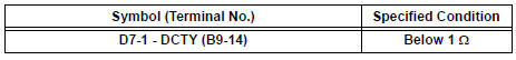
7 CHECK HARNESS AND CONNECTOR (FRONT DOOR COURTESY LIGHT SWITCH - DRIVER SIDE J/B)
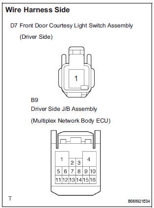
- Disconnect the D7 switch and B9 body ECU connectors.
- Measure the resistance according to the value(s) in the table below.
Standard resistance
REPLACE DRIVER SIDE JUNCTION BLOCK ASSEMBLY (MULTIPLEX NETWORK BODY ECU)
 All Doors cannot be Locked / Unlocked at Once
DESCRIPTION
The body ECU receives a switch signal from the master switch, the door
control switch, the driver door
key cylinder and the passenger door key cylinder and then drives the door lock
...
 Only Back Door cannot be Opened
DESCRIPTION
With power back door: The signal for manual locking/unlocking operation of
the driver/passenger side
door and the signal for locking/unlocking operation interlocked with the driver
s ...
Other materials:
Absence of Registration Unit/ No Response for Connection Check/ Last Mode
Error/ No Response Against ON / OFF Command/ Mode Status Error/ Slave Reset
DTC 01-D5 Absence of Registration Unit
DTC 01-D8 No Response for Connection Check
DTC 01-D9 Last Mode Error
DTC 01-DA No Response Against ON / OFF Command
DTC 01-DB Mode Status Error
DTC 01-DE Slave Reset
DESCRIPTION
HINT:
*1: Even if no fault is present, this trouble code may b ...
When stopping the engine with the shift lever in a position other
than P
If the engine is stopped with the shift lever in a position other than P,
the engine switch will not be turned off but instead be turned to
ACCESSORY mode. Perform the following procedure to turn the
switch off:
Check that the parking brake is set.
Shift the shift lever to P.
Check that t ...
Throttle Actuator Control System
DTC P2111 Throttle Actuator Control System - Stuck Open
DTC P2112 Throttle Actuator Control System - Stuck
Closed
DESCRIPTION
The throttle actuator is operated by the ECM, and opens and closes the
throttle valve using the gears.
The opening angle of the throttle valve is detected by the Thr ...
