Toyota Sienna Service Manual: Light Sensor Circuit Malfunction
DTC B1244 Light Sensor Circuit Malfunction
DESCRIPTION
This DTC is output when failure in the light sensor circuit is detected.
|
DTC No. |
DTC Detection Condition |
Trouble Area |
|
B1244 |
|
|
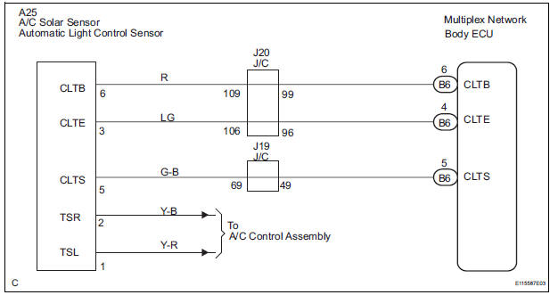
WIRING DIAGRAM
INSPECTION PROCEDURE
1 READ VALUE OF INTELLIGENT TESTER
- Connect the intelligent tester to DLC3.
- Turn the ignition switch ON and push the intelligent tester main switch ON.
- Select the items below in the DATA LIST, and read the displays on the intelligent tester
BODY NO.1:

2 CHECK HARNESS AND CONNECTOR (MULTIPLEX NETWORK BODY ECU - AUTOMATIC LIGHT CONTROL SENSOR)
- Check for open or short circuit in the harness and the connector between the terminal 6 of the automatic light control sensor and the terminal B6-6 of the multiplex network body ECU.
- Check for open or short circuit in the harness and the connector between the terminal 3 of the automatic light control sensor and the terminal B6-4 of the multiplex network body ECU.
- Check for open or short circuit in the harness and the connector between the terminal 5 of the automatic light control sensor and the terminal B6-5 of the multiplex network body ECU
3 INSPECT AUTOMATIC LIGHT CONTROL SENSOR
- Measure voltage between the terminal 3 and the terminal 5 of the automatic light control sensor
Standard

4 INSPECT INSTRUMENT PANEL JUNCTION BLOCK ASSEMBLY
- Measure voltage between the terminal B6-6 and the terminal B6-4 of the multiplex network body ECU in the instrument panel junction block assembly.
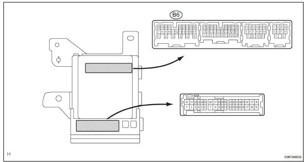
Voltage

REPLACE AUTOMATIC LIGHT CONTROL SENSOR
 Diagnostic trouble code chart
1. DTC CHECK
If a malfunction code is displayed during the DTC check ,
check the suspected area listed for that code in the table
below, and proceed to the appropriate page.
DIAGNOSTIC TROUBLE COD ...
 Ignition Switch Circuit
DESCRIPTION
The Multiplex network body ECU receives the ACC and IG signals from the
ignition switch.
WIRING DIAGRAM
INSPECTION PROCEDURE
1 READ VALUE OF INTELLIGENT TESTER
Connect the in ...
Other materials:
Rear evaporator temperature sensor circuit
DESCRIPTION
The rear evaporator temperature sensor is installed on the rear evaporator.
It detects the rear evaporator
temperature. The sensor sends a signal to the A/C amplifier. The resistance of
the rear evaporator
temperature sensor changes in accordance with the rear evaporator temperatu ...
Operating the HomeLink
Press the appropriate HomeLinkÂź button. The HomeLinkÂź indicator
light on the HomeLinkÂź transceiver should turn on.
The HomeLinkÂź continues to send a signal for up to 20 seconds as long as
the button is pressed.
Reprogramming a HomeLinkÂź button
Press and hold the desired HomeLinkÂź button ...
Receiving a call
When a call is received, the following screen is displayed
together with a sound.
To answer the phone
Press the switch on the steering
wheel or select .
To refuse a call
Press the switch on the steering
wheel or select
To adjust the incoming call volume
Turn the âPWRâąVOLâ knob ...
