Toyota Sienna Service Manual: Low Battery Positive Voltage
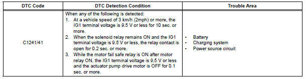
DTC C1241/41 Low Battery Positive Voltage
DESCRIPTION
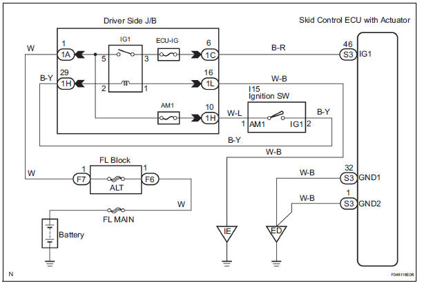
WIRING DIAGRAM
INSPECTION PROCEDURE
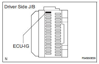
1 INSPECT ECU-IG FUSE
(a) Remove the ECU-IG fuse from the driver side J/B.
(b) Check continuity of the ECU-IG fuse.
Standard resistance


2 CHECK BATTERY
(a) Check the positive battery voltage.
Standard voltage: 11 to 14 V

3 INSPECT SKID CONTROL ECU (IG1 TERMINAL)
(a) WHEN USING INTELLIGENT TESTER: (1) Connect the intelligent tester to the DLC3.
(2) Start the engine.
(3) Select the DATA LIST mode on the intelligent tester.
ABS / VSC:
(4) Check that the voltage condition output from the ECU displayed on the intelligent tester.
OK: "Normal" is displayed.
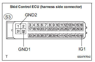
(b) WHEN NOT USING INTELLIGENT TESTER: (1) Disconnect the skid control ECU connector.
(2) Turn the ignition switch to the ON position.
(3) Measure the voltage according to the value(s) in the table below.
Standard voltage 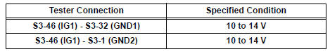
NOTICE: When replacing the brake actuator assembly, perform zero point calibration (See page BC-70).

REPLACE BRAKE ACTUATOR ASSEMBLY
4 INSPECT SKID CONTROL ECU (GND TERMINAL)
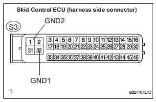
(a) Disconnect the skid control ECU connector.
(b) Measure the resistance according to the value(s) in the table below.
Standard resistance 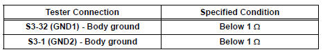

REPAIR OR REPLACE HARNESS OR CONNECTOR (IG1 CIRCUIT)
 Stuck in Deceleration Sensor
DESCRIPTION
The yaw rate sensor and deceleration sensor signal is sent to the skid
control ECU through the CAN
communication system. When there is a malfunction in the communication, it will
...
 Master Cylinder Pressure Sensor Malfunction
DTC C1246/46 Master Cylinder Pressure Sensor Malfunction
DESCRIPTION
Master cylinder pressure sensor is connected to the skid control ECU in the
actuator.
INSPECTION PROCEDURE
1 READ VALUE O ...
Other materials:
U151f automatic transaxle
SST
RECOMMENDED TOOLS
EQUIPMENT
LUBRICANT
SSM
...
Disposal
HINT:
Use the same procedures for the RH side and LH side.
The procedures listed below are for the LH side.
When scrapping a vehicle equipped with the SRS or
disposing of the curtain shield airbag assembly, be sure to
deploy the airbag first in accordance with the procedure
described b ...
Radiator
COMPONENTS
...
