Toyota Sienna Service Manual: Manual Up / Down Function does not Operate on Rear LH Only
DESCRIPTION
If the manual UP/DOWN function does not operate, the power window motor, the regulator switch or the wire harness may be malfunctioning.
WIRING DIAGRAM
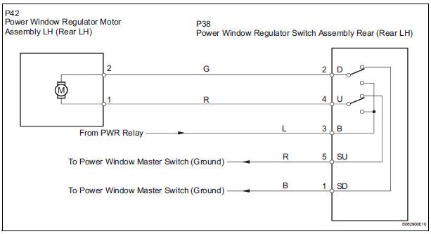
INSPECTION PROCEDURE
1 CHECK WIRE HARNESS (POWER SOURCE)
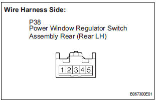
- Disconnect the P38 regulator switch connector.
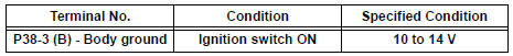
- Turn the ignition switch ON.
- Check the voltage between the terminal 4 of the wire harness side connector and the body ground.
Standard voltage
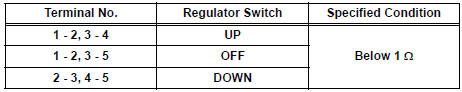
2 INSPECT POWER WINDOW REGULATOR SWITCH (REAR LH)
- Remove the regulator switch.
- Check the resistance between the switch terminals when the switch is operated, as shown in the table below.
Standard resistance
3 CHECK WIRE HARNESS (REGULATOR SWITCH - MOTOR) (REGULATOR SWITCH - BODY GROUND)
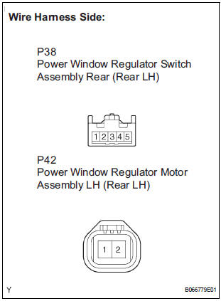
- Disconnect the P42 motor connector.
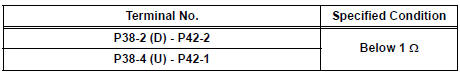
- Check the resistance between the wire harness side connectors.
Standard resistance
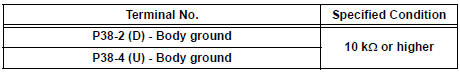
- Check the resistance between the P38 regulator switch connector and body ground.
Standard resistance
4 INSPECT POWER WINDOW REGULATOR MOTOR ASSEMBLY (REAR LH)
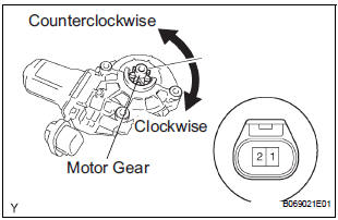
- Remove the motor.
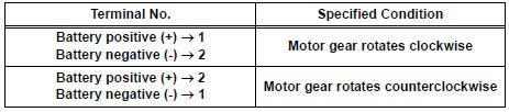
- Apply battery voltage to connector terminals 1 and 2.
- Check that the motor smoothly rotates.
NOTICE: Do not apply battery voltage to any terminals except terminals 1 and 2.
Standard
REPAIR OR REPLACE HARNESS AND CONNECTOR (MASTER SWITCH - REGULATOR SWITCH)
 Manual Up / Down and Auto Down Function does not Operate on
Passenger Side Only
Manual Up / Down and Auto Down Function does not Operate on
Passenger Side Only
DESCRIPTION
If the manual UP/DOWN function does not operate, the power window motor, the
regulator switch or the
wire harness may be malfunctioning.
WIRING DIAGRAM
INSPECTION PROCEDURE
1 CH ...
 Manual Up / Down Function does not Operate on Rear RH Only
DESCRIPTION
If the manual UP/DOWN function does not operate, the power window motor, the
regulator switch or the
wire harness may be malfunctioning.
WIRING DIAGRAM
INSPECTION PROCEDURE
1 CH ...
Other materials:
Checking tires
Check if the treadwear indicators are showing on the tires. Also check
the tires for uneven wear, such as excessive wear on one side of the
tread. Check the spare tire condition and pressure if not rotated.
New tread
Worn tread
Treadwear indicator
The location of treadwear indicator ...
Low Battery Positive Voltage
DTC C1241/41 Low Battery Positive Voltage
DESCRIPTION
If there is a problem with the brake actuator assembly (skid control ECU)
power supply circuit, the skid
control ECU outputs the DTC and prohibits the ABS operation with the fail safe
function.
If the voltage supplied to the IG1 termina ...
Multiplex Communication Circuit
DESCRIPTION
INSPECTION PROCEDURE
1 GO TO CAN COMMUNICATION SYSTEM
(a) Refer to the CAN communication system (See page CA-
7).
(b) If the CAN communication system is operating normally,
proceed to the next step.
2 GO TO MULTIPLEX COMMUNICATION SYSTEM (BEAN)
(a) Refer to the multiplex com ...
