Toyota Sienna Service Manual: Mass air flow meter
COMPONENTS
ON-VEHICLE INSPECTION
1. INSPECT MASS AIR FLOW METER
NOTICE:
|
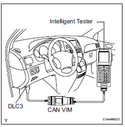
(a) Read the values using the intelligent tester (MAF).
NOTICE:
|
(1) Turn the ignition switch to the ON position (do not start the engine).
(2) Turn the tester on.
(3) Select the following menu items: DIAGNOSIS / ENHANCED OBD II / DATA LIST / PRIMARY / PRIMARY / MAF.
(4) Wait 30 seconds, and read the values on the intelligent tester.
Standard condition: Less than 0.70 g/s
- If the result is not as specified, replace the MAF meter.
- If the result is within the specified range, inspect the cause of the extremely rich or lean air fuel ratio.
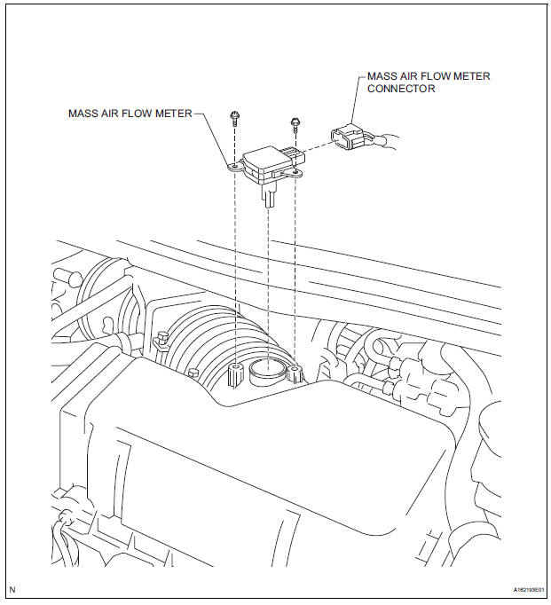
REMOVAL
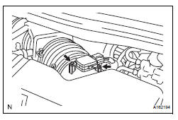
1. REMOVE MASS AIR FLOW METER
(a) Disconnect the mass air flow meter connector.
(b) Remove the 2 screws and mass air flow meter.
INSPECTION
1. INSPECT MASS AIR FLOW METER
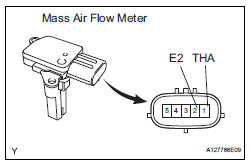
(a) Visually check for any foreign matter on the platinum hot wire (heater) of the mass air flow meter.
OK: There is no foreign matter.
If the result is not as specified, replace the mass air flow meter.
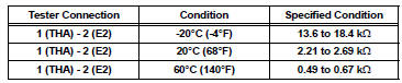
(b) Measure the resistance according to the value(s) in the table below.
Standard resistance
INSTALLATION
1. REMOVE MASS AIR FLOW METER
(a) Install the mass air flow meter with the 2 screws.
(b) Connect the mass air flow meter connector.
 Accelerator pedal rod
COMPONENTS
ON-VEHICLE INSPECTION
1. CHECK ACCELERATOR PEDAL ROD
(a) Check the voltage.
(1) Connect the intelligent tester to the DLC3.
(2) Turn the ignition switch to the ON position.
...
 Vvt sensor
COMPONENTS
ON-VEHICLE INSPECTION
1. CHECK VVT SENSOR OUTPUT VOLTAGE
(a) Turn the ignition switch to the ON position.
(b) Check the voltage between the specified terminal
and body grou ...
Other materials:
Engine Coolant Temperature Circuit
DTC P0115 Engine Coolant Temperature Circuit
DTC P0117 Engine Coolant Temperature Circuit Low Input
DTC P0118 Engine Coolant Temperature Circuit High Input
DESCRIPTION
A thermistor is built into the Engine Coolant Temperature (ECT) sensor, of
which the resistance value
varies according to the ...
Reassembly
1. INSTALL TRANSFER DRIVEN PINION REAR BEARING
(a) Using SST(s) and a press, install the transfer driven
pinion rear bearing outer race to the transfer case.
SST 09950-60010 (09951-00620), 09950-70010
(09951-07150)
NOTICE:
Place something like wood blocks under the
case to keep its level. ...
Master Error
DTC 01-DF Master Error
DESCRIPTION
DTC No.
DTC Detection Condition
Trouble Area
01-DF
*1
The device with a display fails and the master is
switched to the audio device.
A communication error between sub-master (radio
receiver) and ...
