Toyota Sienna Service Manual: Master Cylinder Pressure Sensor Malfunction
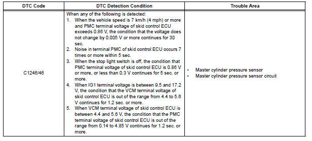
DTC C1246/46 Master Cylinder Pressure Sensor Malfunction
DESCRIPTION
Master cylinder pressure sensor is connected to the skid control ECU in the actuator.
INSPECTION PROCEDURE
1 READ VALUE ON INTELLIGENT TESTER (MASTER CYLINDER PRESSURE SENSOR)
(a) Connect the intelligent tester to the DLC3.
(b) Start the engine.
(c) Select the DATA LIST mode on the intelligent tester.
ABS / VSC: 
(d) Check that the brake fluid pressure value of the master cylinder pressure sensor indicated on the intelligent tester, changes when the brake pedal is depressed.
OK: Brake fluid pressure value should change.
NOTICE: When replacing the brake actuator assembly, perform zero point calibration (See page BC-70).

REPLACE BRAKE ACTUATOR ASSEMBLY
2 INSPECT SKID CONTROL ECU (STP1 TERMINAL)
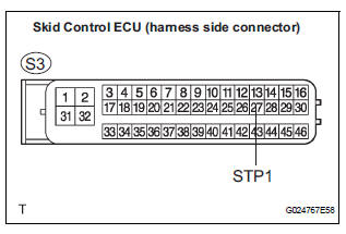
(a) Disconnect the skid control ECU connector.
(b) Measure the voltage according to the value(s) in the table below
Standard voltage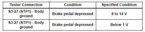
NOTICE: When replacing the brake actuator assembly, perform zero point calibration (See page BC-70).
REPLACE BRAKE ACTUATOR ASSEMBLY
 Low Battery Positive Voltage
DTC C1241/41 Low Battery Positive Voltage
DESCRIPTION
WIRING DIAGRAM
INSPECTION PROCEDURE
1 INSPECT ECU-IG FUSE
(a) Remove the ECU-IG fuse from the driver side J/B.
(b) Check continu ...
 Open in Stop Light Switch Circuit
DTC C1249/49 Open in Stop Light Switch Circuit
DESCRIPTION
WIRING DIAGRAM
INSPECTION PROCEDURE
1 CHECK STOP LIGHT SWITCH OPERATION
(a) Check that the stop light comes on when the brak ...
Other materials:
Diagnosis system
1. CHECK DLC3
The ECU uses the ISO 15765-4 for communication
protocol. The terminal arrangement of the DLC3
complies with SAE J1962 and matches the ISO
15765-4 format.
NOTICE:
*: Before measuring the resistance, leave the
vehicle as is for at least 1 minute and do not
ope ...
Installation
1. Install air fuel ratio sensor (for bank 2
sensor 1)
(a) Using SST, install the sensor to the exhaust
manifold LH.
SST 09224-00010
Torque: 40 N*m (408 kgf*cm, 30 ft.*lbf) for use
with SST
44 N*m (449 kgf*cm, 32 ft.*lbf) for use
without SST
HINT:
Use a torque wrench with a fulcrum ...
Installation
1. Install heated oxygen sensor (for bank 2
sensor 2) (see page ec-34)
2. Install front exhaust pipe assembly
(a) Install 2 new gaskets to the front exhaust pipe
assembly.
(b) Install the front exhaust pipe assembly with the 4
nuts.
Torque: 62 n*m (632 kgf*cm, 46 ft.*Lbf)
3. INSTALL CE ...
