Toyota Sienna Service Manual: Memory Switch Circuit
DESCRIPTION
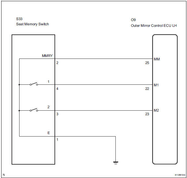
When the seat memory switch M1 or M2 is pressed, the position control ECU & switch (Seat ECU) transmits a signal of the memorized mirror position to the outer mirror control ECU. Then, the outer mirror control ECU drives the mirror motor.
HINT: The power mirror control system is a part of the multiplex communication system. This system features shared communication wiring that reduces the wiring complexity of the communication lines. The first step in any repair is to confirm the proper operation of the communication system. Proceed with troubleshooting after the communication has been verified (See the Multiplex Communication System).
WIRING DIAGRAM
INSPECTION PROCEDURE
1 READ VALUE OF INTELLIGENT TESTER
- Connect the intelligent tester to the DLC3.
- Ignition switch on.
- Enter the following menus: DIAGNOSIS / ENHANCED OBD II / DATA LIST.
- Check the DATA LIST for proper function of the seat memory switch.
D-SEAT
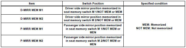
OK: Tester displayed MEM.
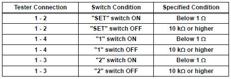
2 INSPECT SEAT MEMORY SWITCH
- Remove the seat memory switch.
- Measure the resistance according to the value(s) in the table below when the switch is operated.
Standard resistance
3 CHECK HARNESS AND CONNECTOR (SEAT MEMORY SWITCH - OUTER MIRROR CONTROL ECU)
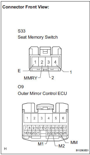
- Disconnect the S33 switch connector.
- Disconnect the O9 ECU connector.
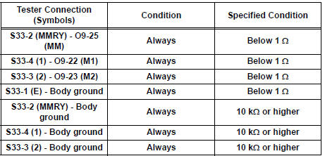
- Measure the resistance according to the value(s) in the table below.
Resistance
REPLACE OUTER MIRROR CONTROL ECU
 Position Sensor Circuit
DESCRIPTION
When SET and 1 or 2 are pressed, the position sensor detects the mirror
position and sends the signal to
the outer mirror control ECU. Then when position 1 or 2 is pressed, the outer
...
 Power Source Circuit
DESCRIPTION
This is the power source circuit for the outer mirror control ECU.
WIRING DIAGRAM
INSPECTION PROCEDURE
1 INSPECT OUTER MIRROR CONTROL ECU (POWER SOURCE)
Disconnect the O9 o ...
Other materials:
Reassembly
1. INSTALL RACK STEERING PISTON RING
(a) Coat a new O-ring with power steering fluid and
install it onto the power steering rack.
(b) Expand a new rack steering piston ring with your
fingers.
NOTICE:
Be careful not to over expand the rack steering
piston ring.
(c) Coat a new rack steer ...
TC and CG Terminal Circuit
DESCRIPTION
Connecting terminals TC and CG of the DLC3 causes the ECU to display the DTC
by blinking the ABS
warning light and/or VSC warning light.
WIRING DIAGRAM
INSPECTION PROCEDURE
NOTICE:
When replacing the brake actuator assembly, perform zero point calibration
(See page BC-70).
...
Identification of noise source
1. Radio Description
Radio frequency band
Radio broadcasts use the radio frequency bands
shown in the table below.
Service area
The service areas of AM and FM broadcasts are
vastly different. Sometimes an AM broadcast
can be received very clearly ...
