Toyota Sienna Service Manual: Meter Illumination does not Dim at Night
DESCRIPTION
- Confirm that the vehicle is equipped with the optitron meter, then check this circuit.
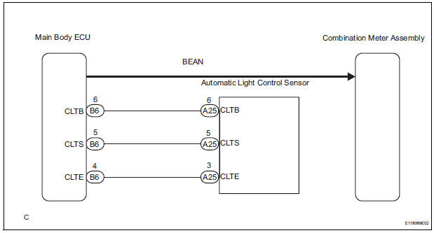
- The combination meter assembly receives a auto dimmer signal from the body ECU by the multiplex communication line.
WIRING DIAGRAM
INSPECTION PROCEDURE
1 CHECK MULTIPLEX COMMUNICATION SYSTEM
- Check if MULTIPLEX communication DTC is output
Result

2 CHECK DTC
- Check if the DTC B1244 is output
Result

3 PERFORM ACTIVE TEST BY INTELLIGENT TESTER
- Operate the intelligent tester according to the steps on the display and select "DATA LIST".
MAIN BODY

OK: The meter illumination is dimmed when the DIMMER SIG is ON.
CHECK LIGHTING SETTING
4 REPLACE COMBINATION METER ASSEMBLY
OK: The operation of the combination meter assembly returns to normal.
END
 Meter Illumination is Always Dark
DESCRIPTION
Confirm that the vehicle is equipped with the optitron meter, then
check this circuit.
The combination meter assembly receives a auto dimmer signal from the
body ECU by t ...
 Combination meter
COMPONENTS
...
Other materials:
Air Mix Damper Position Sensor Circuit (Driver Side)
DESCRIPTION
This sensor detects the position of the air mix control servo motor (air
outlet damper) and sends the
appropriate signals to the A/C amplifier. The position sensor is built in the
air mix control servo motor. The
position sensor resistance changes as the air mix control servo ...
If the engine will not
start
If the engine will not start even though correct starting procedures
are being followed (, 228), consider each of the following
points:
The engine will not start even though the starter motor operates
normally.
One of the following may be the cause of the problem:
There may not be sufficien ...
Inspection
1. INSPECT NO. 1 VALVE ROCKER ARM SUBASSEMBLY
(a) Turn the roller by hand to check that it turns
smoothly.
HINT:
If the roller does not turn smoothly, replace the valve
rocker arm sub-assembly.
2. INSPECT VALVE LASH ADJUSTER ASSEMBLY
NOTICE:
Keep the lash adjuster free of dirt ...
