Toyota Sienna Service Manual: Mute Signal Circuit between Radio and Navigation Assembly and Stereo Component Amplifier
DESCRIPTION
This circuit sends a signal to the stereo component amplifier to mute noise. Because of that, the noise produced by changing the sound source ceases.
If there is an open in the circuit, noise can be heard from the speakers when changing the sound source.
If there is a short in the circuit, even though the stereo component amplifier is normal, no sound, or only an extremely small sound, can be produced.
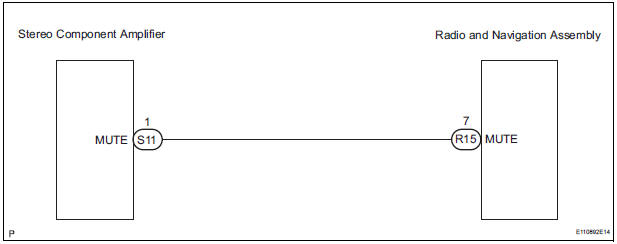
WIRING DIAGRAM
INSPECTION PROCEDURE
1 INSPECT STEREO COMPONENT AMPLIFIER
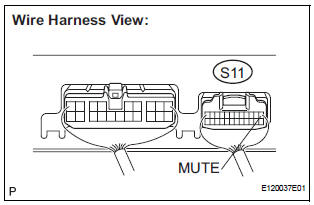
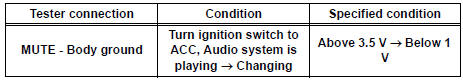
- Measure the voltage according to the value(s) in the table below.
Standard voltage
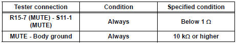
2 CHECK HARNESS AND CONNECTOR (RADIO AND NAVIGATION ASSEMBLY - STEREO COMPONENT AMPLIFIER)
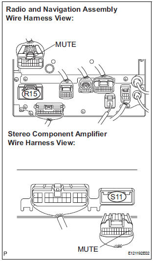
- Disconnect the radio and navigation assembly connector R15 and television display assembly connector S11.
- Measure the resistance according to the value(s) in the table below.
Standard resistance
3 REPLACE STEREO COMPONENT AMPLIFIER
- Replace the stereo component amplifier and check if it operates normally.
OK: The navigation system operates normally
REPLACE RADIO AND NAVIGATION ASSEMBLY
 Mute Signal Circuit between Radio and Navigation Assembly and
Television Display Assembly
Mute Signal Circuit between Radio and Navigation Assembly and
Television Display Assembly
DESCRIPTION
The radio and navigation assembly controls the volume according to the MUTE
signal from the television
display assembly.
The MUTE signal is sent to reduce noise and a popping sound ...
 AVC-LAN Circuit
DESCRIPTION
Each unit of the navigation system connected to the AVC-LAN (communication
bus) transfers the signal of
each switch by communication.
When a short to +B or short to ground occurs in ...
Other materials:
Right Front Wheel Speed Sensor Signal
DESCRIPTION
The speed sensor detects wheel speed and sends the appropriate signals to the
ECU. These signals are
used to control the ABS control system. The front and rear rotors have 48
serrations each.
When the rotors rotate, the magnetic field emitted by the permanent magnet in
t ...
Air Intake Control Circuit
DESCRIPTION
The air cleaner is equipped with two inlets, one of which is opened or closed
by the Air Intake Control
Valve (AICV). This system reduces intake noise and increases engine power at
low-to-high engine speed
range.
When the engine is operating in the low-to-mid speed range, this ...
Adjustment
1. INSPECT SHIFT LEVER POSITION
(a) When shifting from P to R position only with ignition
switch ON and brake pedal, make sure that the
shifting lever moves smoothly and can be
moderately operated.
(b) When starting engine, make sure that the vehicle
moves forward when shifting from N to D p ...
