Toyota Sienna Service Manual: No. 2 Clearance Warning Buzzer Circuit
DESCRIPTION
The clearance warning ECU receives the ultrasonic sensor signal to sound the rear warning buzzer.
WIRING DIAGRAM
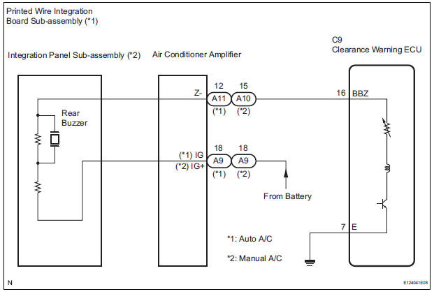
INSPECTION PROCEDURE
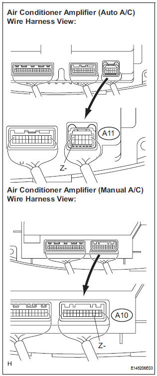
1 CHECK HARNESS AND CONNECTOR (CLEARANCE WARNING ECU - AIR CONDITIONER AMPLIFIER)
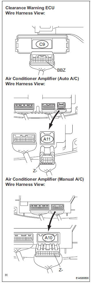
- Disconnect the connectors from the clearance warning ECU C9 and air conditioner amplifier connector A10 or A11.
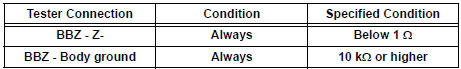
- Measure the resistance according to the value(s) in the table below.
Standard resistance
2 INSPECT REAR BUZZER
- Remove the integration control & panel assembly with the connectors still connected.
- Using a service wire, ground the terminal Z- of the integration control & panel assembly connector.
- Turn the ignition switch ON.
- Check that the rear buzzer sounds.
HINT: The clearance warning buzzer is separately excited, and will not sound unless an alternating voltage is applied.
OK: Operating noise (clicking sounds) can be heard.
Result
PROCEED TO NEXT CIRCUIT INSPECTION SHOWN IN PROBLEM SYMPTOMS TABLE
3 INSPECT PRINTED WIRE INTEGRATION BOARD SUB-ASSEMBLY
- Check that the malfunction disappears when a known good printed wire integration board sub-assembly is installed.
OK: Malfunction disappears.
REPLACE PRINTED WIRE INTEGRATION BOARD SUB-ASSEMBLY
4 INSPECT INTEGRATION PANEL SUB-ASSEMBLY
- Check that the malfunction disappears when a known good integration panel sub-assembly is installed.
OK: Malfunction disappears
REPLACE INTEGRATION PANEL SUB-ASSEMBLY
 Clearance Warning ECU Power Source Circuit
DESCRIPTION
This circuit provides power to the clearance warning ECU.
WIRING DIAGRAM
INSPECTION PROCEDURE
1 CHECK HARNESS AND CONNECTOR (CLEARANCE WARNING ECU - AIR CONDITIONER
AMPLIFIER)
...
 Indicator Circuit
DESCRIPTION
The indicator displays the location of the obstacle and the approximate
distance between the vehicle and
the obstacle either by blinking or turning on.
WIRING DIAGRAM
INSPECTION ...
Other materials:
Short to GND in Driver Side Squib Circuit
DTC B0102/11 Short to GND in Driver Side Squib Circuit
DESCRIPTION
The driver side squib circuit consists of the center airbag sensor assembly,
the spiral cable and the
steering pad.
The circuit instructs the SRS to deploy when deployment conditions are met.
DTC B0102/11 is recorded when ...
Removal
1. Remove rear wheel
2. Remove skid control sensor wire (for 2wd)
Hint:
(see page sp-38)
hint:
disconnect the rh side by the same procedures as the
lh side.
3. SEPARATE SPEED SENSOR REAR LH (for 4WD)
HINT:
(See page SP-38)
4. SEPARATE SPEED SENSOR REAR RH (for 4WD)
HINT:
Separate the RH ...
Air conditioning controls
Adjusting the temperature setting
Turn the “TEMP” dial clockwise to increase the temperature and
counterclockwise to decrease the temperature.
The “SYNC” button
The air conditioning system switches between individual (indicator(
s) off) and simultaneous (indicators on) modes.
Whe ...
