Toyota Sienna Service Manual: On-vehicle inspection
1. CONNECT INTELLIGENT TESTER
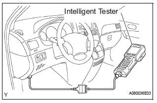
(a) Connect the intelligent tester to the DLC3.
(b) Start the engine and run at idle.
(c) Select the ACTIVE TEST mode on the intelligent tester.
HINT: Please refer to the intelligent tester operator's manual for further details.
2. INSPECT ACTUATOR MOTOR OPERATION
(a) With the motor relay on, check the actuator motor operation noise.
(b) Turn the motor relay off.
(c) Depress the brake pedal and hold it for approximately 15 seconds. Check that the brake pedal cannot be depressed.
(d) With the motor relay on, check that the pedal does not pulsate.
NOTICE: Do not keep the motor relay turned on for more than 5 seconds continuously. When operating it continuously, set an interval of more than 20 seconds.
(e) Turn the motor relay off and release the brake pedal.
3. INSPECT RIGHT FRONT WHEEL OPERATION
NOTICE: Never turn on the solenoids in a manner different to those described below.
(a) With the brake pedal depressed, perform the following operations.
(b) Turn the SFRH and SFRR solenoids on simultaneously, and check that the pedal cannot be depressed.
NOTICE: Do not keep the solenoid turned on for more than 10 seconds continuously. When operating it continuously, set an interval of more than 20 seconds.
(c) Turn the SFRH and SFRR solenoids off simultaneously, and check that the pedal can be depressed.
(d) Turn the motor relay on, and check that the pedal returns.
NOTICE: Do not keep the motor relay turned on for more than 5 seconds continuously. When operating it continuously, set an interval of more than 20 seconds.
(e) Turn the motor relay off and release the brake pedal.
4. INSPECT OTHER WHEEL OPERATION
(a) Using the same procedure, check the solenoids of the other wheels.
HINT: Left front wheel: SFLH, SFLR Right rear wheel: SRRH, SRRR Left rear wheel: SRLH, SRLR
 Brake actuator (w/ vsc)
Components
...
 Removal
1. DRAIN BRAKE FLUID
NOTICE:
Wash brake fluid off immediately if it adheres to any
painted surface.
2. DISCONNECT BATTERY NEGATIVE TERMINAL
3. REMOVE AIR CLEANER ASSEMBLY WITH HOSE
4. REMOVE BRA ...
Other materials:
Problem symptoms table
Before inspecting the suspected areas listed in the table
below, check the fuse and relay.
Before inspecting the suspected areas listed in the table
below, check the DTCs.
Methods used to verify the cause of the problem are listed
in order of probability in the suspected are ...
Removal
1. DISCONNECT CABLE FROM NEGATIVE BATTERY
TERMINAL
2. REMOVE FRONT BUMPER ASSEMBLY
Remove the 4 screws and separate the fender liner
from the front bumper assembly.
Remove the 8 screws and separate the engine
under cover from the front bumper assembly.
Remove the 5 ...
Brake System Malfunction
DTC P1578 Brake System Malfunction
DESCRIPTION
This DTC is output when the VSC system has a problem. Check the VSC system
when this DTC is
output
DTC No.
DTC Detection Condition
Trouble Area
P1578
The ECM receives a brake system error signal for 0.2
...
