Toyota Sienna Service Manual: On-vehicle inspection
1. CONNECT INTELLIGENT TESTER
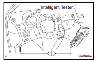
(a) Connect the intelligent tester to the DLC3.
(b) Start the engine and run at idle.
(c) Select the ACTIVE TEST mode on the intelligent tester.
HINT: Please refer to the intelligent tester operator's manual for further details.
2. INSPECT ACTUATOR MOTOR OPERATION
(a) With the motor relay on, check the actuator motor operation noise.
(b) Turn the motor relay off.
(c) Depress the brake pedal and hold it for approximately 15 seconds. Check that the brake pedal cannot be depressed.
(d) With the motor relay on, check that the pedal does not pulsate.
NOTICE: Do not keep the motor relay turned on for more than 5 seconds continuously. When operating it continuously, set an interval of more than 20 seconds.
(e) Turn the motor relay off and release the brake pedal.
3. INSPECT RIGHT FRONT WHEEL OPERATION
NOTICE: Never turn on the solenoids in a manner different to those described below.
(a) With the brake pedal depressed, perform the following operations.
(b) Turn the SFRH and SFRR solenoids on simultaneously, and check that the pedal cannot be depressed.
NOTICE: Do not keep the solenoid turned on for more than 10 seconds continuously. When operating it continuously, set an interval of more than 20 seconds
(c) Turn the SFRH and SFRR solenoids off simultaneously, and check that the pedal can be depressed.
(d) Turn the motor relay on, and check that the pedal returns.
NOTICE: Do not keep the motor relay turned on for more than 5 seconds continuously. When operating it continuously, set an interval of more than 20 seconds.
(e) Turn the motor relay off and release the brake pedal.
4. INSPECT OTHER WHEEL OPERATION
(a) Using the same procedure, check the solenoids of the other wheels.
HINT: Left front wheel: SFLH, SFLR Right rear wheel: SRRH, SRRR Left rear wheel: SRLH, SRLR
 Brake actuator (w/o vsc)
Components
...
 Removal
1. DRAIN BRAKE FLUID
NOTICE:
Wash brake fluid off immediately if it adheres to any
painted surface.
2. DISCONNECT BATTERY NEGATIVE TERMINAL
3. REMOVE AIR CLEANER ASSEMBLY WITH HOSE
4. REMOVE BRA ...
Other materials:
Perform zero point calibration of yaw rate and deceleration sensor (when
using sst check wire)
NOTICE:
While obtaining the zero point, do not vibrate the
vehicle by tilting, moving or shaking it and keep it
in a stationary condition. (Do not turn the ignition
switch to the ON position.)
Be sure to do this on a level surface (with an
inclination of less than 1 %).
(a) Proc ...
Installation
1. INSTALL TIMING CHAIN CASE OIL SEAL
(a) Using SST, tap in a new oil seal until its surface is
flush with the timing chain case edge.
SST 09223-22010, 09506-35010
NOTICE:
Keep the lip free from foreign matter.
Do not tap on the oil seal at an angle.
Make sure that the oil ...
Side Airbag Sensor Assembly LH Circuit Malfunction
DTC B1141/33 Side Airbag Sensor Assembly LH Circuit Malfunction
DESCRIPTION
The side airbag sensor LH circuit consists of the center airbag sensor
assembly and side airbag sensor
LH.
If the center airbag sensor assembly receives signals from the side airbag
sensor LH, it judges whether or
...
