Toyota Sienna Service Manual: On-vehicle inspection
1. INSPECT BRAKE PEDAL HEIGHT
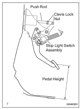
(a) Check the brake pedal height.
Pedal height from dash panel: 150.3 to 160.3 mm (5.917 to 6.311 in.)
NOTICE: Do not adjust the pedal height. Doing so by changing the push rod length will structurally change the pedal ratio.
2. CHECK AND ADJUST STOP LIGHT SWITCH
(a) Disconnect the stop light switch assembly connector from the stop light switch assembly.
(b) Turn the stop light switch assembly counterclockwise and remove the stop light switch assembly.
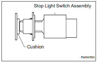
(c) Insert the stop light switch assembly until the body hits the cushion.
NOTICE: When inserting the stop light switch assembly, support the pedal from behind so that the pedal is not pushed in.
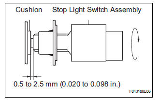
(d) Make a quarter turn clockwise to install the stop light switch assembly.
NOTICE:
- When inserting the stop light switch assembly, support the pedal from behind so that the pedal is not pushed in.
- The turning torque for installing the stop light switch assembly
Torque: 1.5 N*m (15 kgf*cm, 13 in.*lbf) or less
(e) Connect the stop light switch connector to the stop light switch assembly.
(f) Check the protrusion of the rod.
Protrusion of the rod: 0.5 to 2.5mm (0.020 to 0.098 in.)
3. CHECK PEDAL FREE PLAY
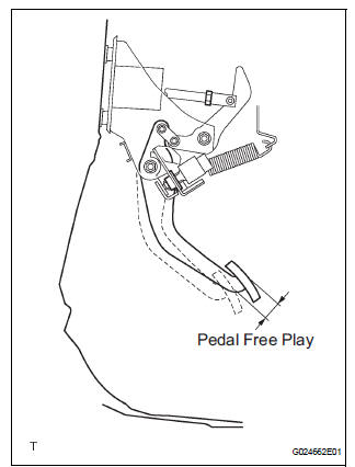
(a) Stop the engine and depress the brake pedal several times until there is no more vacuum left in the booster.
(b) Push in the pedal until the beginning of the resistance is felt. Measure the distance, as shown.
Pedal free play: 1 to 6 mm (0.04 to 0.24 in.)
4. CHECK PEDAL RESERVE DISTANCE
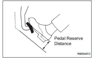
(a) Release the parking brake pedal.
With the engine running, depress the pedal and measure the pedal reserve distance, as shown.
Pedal reserve distance from asphalt sheet at 490 N (50 kgf, 110 lbf): More than 52 mm (2.0 in.)
HINT: If the distance is out of the specification, troubleshoot the brake system.
 Brake pedal
Components
...
 Removal
1. SEPARATE BATTERY NEGATIVE TERMINAL
2. REMOVE FRONT DOOR SCUFF PLATE LH
3. REMOVE COWL SIDE TRIM BOARD LH
4. REMOVE INSTRUMENT PANEL FINISH PANEL SUBASSEMBLY
LOWER LH
(a) Remove the 2 bolts and ...
Other materials:
Diagnostic trouble code chart
Look for output Diagnostic Trouble Codes (DTCs) (from the
DTC checks) in the appropriate section's Diagnostic Trouble
Code Chart. Use the chart to determine the trouble area and
the proper inspection procedure. A description of each of the
chart's columns is shown in the table below.
Ite ...
How to proceed with
troubleshooting
NOTICE:
DTCs for the CAN communication system are as follows:
U0073, U0100, U0122, U0123, U0124, U0126 and U1101.
HINT:
If U0235 or U1102 is output alone, the CAN communication is
normal
1 CHECK AND CLEAR DTCS
HINT:
CAN communication DTCs are output when there is an
open or short in any ...
Diagnosis Circuit
DESCRIPTION
DTC output mode is set by connecting terminals TC and CG of the DLC3.
DTCs are displayed by blinking the SRS warning light.
HINT:
When each warning light stays blinking, a ground short in the
wiring of terminal TC of the DLC3 or an
internal ground short in each ECU is ...
