Toyota Sienna Service Manual: Open in ABS Solenoid Relay Circuit
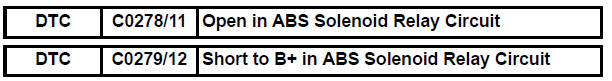
DESCRIPTION
This relay supplies power to each ABS solenoid.
Immediately after the ignition switch is turned to the ON position, the relay turns on if the solenoid is determined to be normal as a result of self-diagnosis during initial check.
The relay turns off if an open/short is detected.
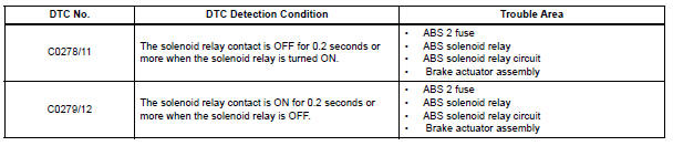
If the voltage supplied to the motor relay (+BS) is below the DTC detection threshold due to low voltage from the battery/alternator, the DTCs may be stored.
WIRING DIAGRAM
Refer to DTCs C0226/21, C0236/22, C0246/23 and C0256/24 (See page BC-29).
INSPECTION PROCEDURE
1 INSPECT FUSE (ABS 2 FUSE)
(a) Remove the ABS 2 fuse from the FL block.
(b) Measure the resistance according to the value(s) in the table below.
Standard resistance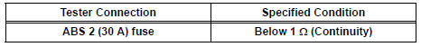


2 INSPECT SKID CONTROL ECU (+BS TERMINAL VOLTAGE)
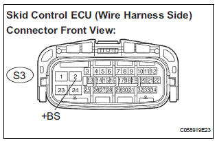
(a) Install the ABS 2 fuse.
(b) Disconnect the skid control ECU connector.
(c) Measure the voltage according to the value(s) in the table below
Standard voltage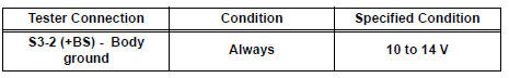

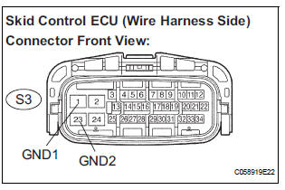
3 INSPECT SKID CONTROL ECU (GND TERMINAL CONTINUITY)
(a) Measure the resistance according to the value(s) in the table below.
Standard resistance 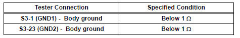

4 RECONFIRM DTC
(a) Clear the DTCs (See page BC-10).
(b) Start the engine.
(c) Drive the vehicle at the speed of 6 km/h (4 mph) or more.
(d) Check that the same DTCs are recorded (See page BC- 10).
HINT:
- Reinstall the sensors, connectors, etc. and restore the vehicle to its prior condition before rechecking for DTCs.
- If a speed signal of 6 km/h (4 mph) or more is input to the skid control ECU, with the ignition switch on and the stop light switch off, the ECU performs selfdiagnosis of the motor and solenoid circuits.
Result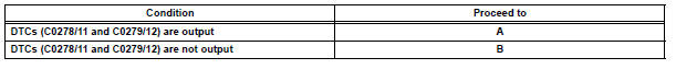
HINT:
- If any DTCs are output while jiggling a connector or wire harness of the brake actuator (skid control ECU), inspect and repair the connector or wire harness.
- If the normal system code is output, slightly jiggle the connectors, wire harnesses, and fuses of the brake actuator assembly. Make sure that no DTCs are output.
- These DTCs may be memorized due to a malfunction in the connector terminal connection, etc.

REPLACE BRAKE ACTUATOR ASSEMBLY
 Open in ABS Motor Relay Circuit
DESCRIPTION
The ABS motor relay supplies power to the ABS pump motor. While the ABS is
activated, the ECU turns
the motor relay on and operates the ABS pump motor.
If the voltage supplied t ...
 Low Battery Positive Voltage
DTC C1241/41 Low Battery Positive Voltage
DESCRIPTION
If there is a problem with the brake actuator assembly (skid control ECU)
power supply circuit, the skid
control ECU outputs the DTC and proh ...
Other materials:
Diagnosis system
1. CHECK DLC3
The vehicle's ECU uses ISO 15765-4 for
communication protocol. The terminal arrangement
of the DLC3 complies with SAE J1962 and matches
the ISO 15765-4 format.
NOTICE:
*: Before measuring the resistance, leave the
vehicle as is for at least 1 minute and do not
...
Disc cannot be Played/ No Playable Files/ Copyright Protection Error
DTC 44-7D Disc cannot be Played
DTC 44-7E No Playable Files
DTC 44-7F Copyright Protection Error
DESCRIPTION
DTC No.
DTC Detecting Condition
Trouble Area
44-7D
An incompatible MP3/WMA file is used.
Although the file has an extension of ".mp3 ...
Side Airbag Sensor Assembly RH Circuit Malfunction
DTC B1140/32 Side Airbag Sensor Assembly RH Circuit Malfunction
DESCRIPTION
The side airbag sensor RH circuit consists of the center airbag sensor
assembly and side airbag sensor
RH.
If the center airbag sensor assembly receives signals from the side airbag
sensor RH, it judges whether or
...
