Toyota Sienna Service Manual: Open in Driver Side Squib 2nd Step Circuit
DTC B1181/18 Open in Driver Side Squib 2nd Step Circuit
DESCRIPTION
The driver side squib 2nd step circuit consists of the center airbag sensor assembly, the spiral cable and the steering pad.
The circuit instructs the SRS to deploy when deployment conditions are met.
DTC B1181/18 is recorded when an open circuit is detected in the driver side squib 2nd step circuit.
|
DTC No. |
DTC Detecting Condition |
Trouble Area |
|
B1181/18 |
|
|
INSPECTION PROCEDURE
HINT:
- Perform the simulation method by selecting the "check mode" (signal check) with the intelligent tester (8).
- After selecting the "check mode" (signal check), perform the simulation method by wiggling each connector of the airbag system or driving the vehicle on a city or rough road
1 CHECK STEERING PAD (DRIVER SIDE SQUIB 2ND STEP)
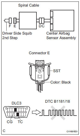
- Turn the ignition switch to the LOCK position.
- Disconnect the negative (-) terminal cable from the battery, and wait for at least 90 seconds.
- Disconnect the connectors from the steering pad.
- Connect the white wire side of SST (resistance 2.1 Ω) to the spiral cable.
CAUTION: Never connect a tester to the steering pad (driver side squib 2nd step) for measurement, as this may lead to a serious injury due to airbag deployment.
NOTICE: Do not forcibly insert the SST into the terminals of the connector when connecting.
Insert the SST straight into the terminals of the connector.
SST 09843-18060
- Connect the negative (-) terminal cable to the battery, and wait for at least 2 seconds.
- Turn the ignition switch to the ON position, and wait for at least 60 seconds.
- Clear the DTCs stored in memory (5).
- Turn the ignition switch to the LOCK position.
- Turn the ignition switch to the ON position, and wait for at least 60 seconds.
- Check the DTCs (5).
OK: DTC B1181/18 is not output. HINT: Codes other than DTC B1181/18 may be output at this time, but they are not related to this check.
 Go to step 2

REPLACE STEERING PAD
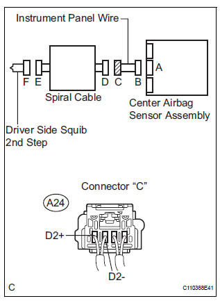
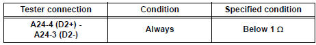
2 CHECK DRIVER SIDE SQUIB 2ND STEP CIRCUIT
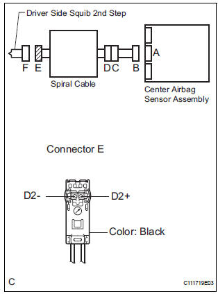
- Turn the ignition switch to the LOCK position.
- Disconnect the negative (-) terminal cable from the battery, and wait for at least 90 seconds.
- Disconnect the SST (resistance 2.1 Ω) from the spiral cable.
- Disconnect the connector from the center airbag sensor assembly.
- Measure the resistance according to the value(s) in the table below.
Standard resistance
 Go to step 4

3 CENTER AIRBAG SENSOR ASSEMBLY
- Connect the connectors to the steering pad and the center airbag sensor assembly.
- Connect the negative (-) terminal cable to the battery, and wait for at least 2 seconds.
- Turn the ignition switch to the ON position, and wait for at least 60 seconds.
- Clear the DTCs stored in memory (5).
- Turn the ignition switch to the LOCK position.
- Turn the ignition switch to the ON position, and wait for at least 60 seconds.
- Check the DTCs (5).
OK: DTC B1181/18 is not output.
HINT: Codes other than DTC B1181/18 may be output at this time, but they are not related to this check.
 REPLACE CENTER AIRBAG SENSOR
ASSEMBLY
REPLACE CENTER AIRBAG SENSOR
ASSEMBLY

USE SIMULATION METHOD TO CHECK
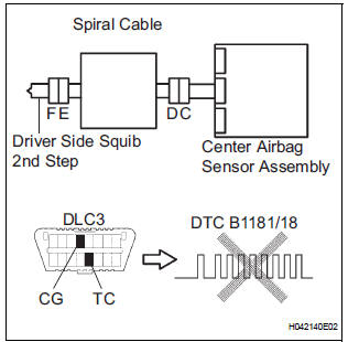
4 CHECK INSTRUMENT PANEL WIRE
- Disconnect the instrument panel wire connector from the spiral cable.
- Measure the resistance according to the value(s) in the table below.
Standard resistance
 REPAIR OR REPLACE INSTRUMENT
PANEL
WIRE
REPAIR OR REPLACE INSTRUMENT
PANEL
WIRE

5 CHECK SPIRAL CABLE
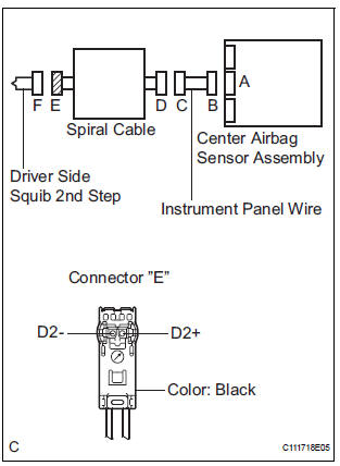
- Measure the resistance according to the value(s) in the table below.
Standard resistance
 REPLACE SPIRAL CABLE

USE SIMULATION METHOD TO CHECK
 Short in Driver Side Squib 2nd Step Circuit
DTC B1180/17 Short in Driver Side Squib 2nd Step Circuit
DESCRIPTION
The driver side squib 2nd step circuit consists of the center airbag sensor
assembly, the spiral cable and
the steering pad.
...
 Short to GND in Driver Side Squib 2nd Step Circuit
DTC B1182/19 Short to GND in Driver Side Squib 2nd Step Circuit
DESCRIPTION
The driver side squib 2nd step circuit consists of the center airbag sensor
assembly, the spiral cable and
the steering ...
Other materials:
Poor Sound Quality in All Modes (Low Volume)
INSPECTION PROCEDURE
1 CHECK AUDIO SETTINGS
Set "BASS", "MID", and "TREB" to the initial values and
check that sound is normal.
OK:
Malfunction disappears.
2 COMPARE WITH ANOTHER VEHICLE OF SAME MODEL
Compare with another vehicle of the same model.
...
On-vehicle inspection
1. INSPECT MASS AIR FLOW METE
NOTICE:
Perform the mass air flow (MAF) meter inspection
by following the procedures below.
Only replace the MAF meter when the MAF value
in the DATA LIST (with the engine stopped) are
not within the normal operating range or there is
fore ...
Disassembly
1. REMOVE FRONT DIFFERENTIAL RING GEAR
(a) Place the match-marks on the ring gear and
differential case.
(b) Remove the 16 bolts.
(c) Using a plastic hammer, tap ring gear to remove it
from the case.
2. REMOVE FRONT DIFFERENTIAL SIDE GEAR
(a) Remove the differential LH case fr ...
