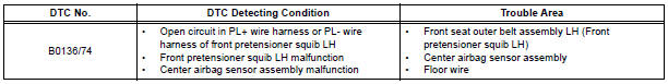
Toyota Sienna Service Manual: Open in Front Pretensioner Squib LH Circuit
DTC B0136/74 Open in Front Pretensioner Squib LH Circuit
DESCRIPTION
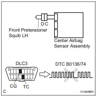
The front pretensioner squib LH circuit consists of the center airbag sensor assembly and the front seat outer belt assembly LH.
This circuit instructs the SRS to deploy when deployment conditions are met.
DTC B0136/74 is recorded when an open circuit is detected in the front pretensioner squib LH circuit.
WIRING DIAGRAM
INSPECTION PROCEDURE
HINT:
- Perform the simulation method by selecting the "check mode" (signal check) with the intelligent tester.
- After selecting the "check mode" (signal check), perform the simulation method by wiggling each connector of the airbag system or driving the vehicle on a city or rough road
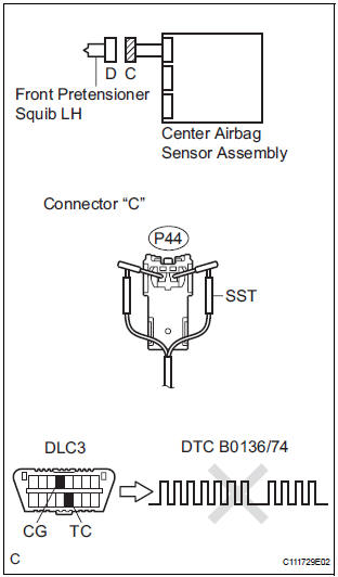
1 CHECK FRONT SEAT OUTER BELT ASSEMBLY LH (FRONT PRETENSIONER SQUIB LH)
- Turn the ignition switch to the LOCK position.
- Disconnect the negative (-) terminal cable from the battery, and wait for at least 90 seconds.
- Disconnect the connectors from the front seat outer belt assembly LH.
- Connect the white wire side of SST (resistance 2.1 Ω) to the floor wire.
CAUTION: Never connect a tester to the front seat outer belt assembly LH (front pretensioner squib LH) for measurement, as this may lead to a serious injury due to airbag deployment.
NOTICE: Do not forcibly insert the SST into the terminals of the connector when connecting.
Insert the SST straight into the terminals of the connector.
SST 09843-18060
- Connect the negative (-) terminal cable to the battery, and wait for at least 2 seconds.
- Turn the ignition switch to the ON position, and wait for at least 60 seconds.
- Clear the DTCs stored in memory.
- Turn the ignition switch to the LOCK position.
- Turn the ignition switch to the ON position, and wait for at least 60 seconds.
- Check the DTCs
OK: DTC B0136/74 is not output.
HINT: Codes other than DTC B0136/74 may be output at this time, but they are not related to this check.
REPLACE FRONT SEAT OUTER BELT ASSEMBLY LH
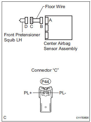
2 CHECK FLOOR WIRE (FRONT PRETENSIONER SQUIB LH CIRCUIT)
- Turn the ignition switch to the LOCK position.
- Disconnect the negative (-) terminal cable from the battery, and wait for at least 90 seconds.
- Disconnect the SST (resistance 2.1 Ω) from the floor wire.
- Disconnect the connector from the center airbag sensor assembly.
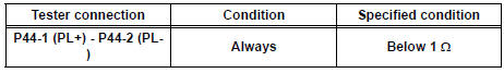
- Measure the resistance according to the value(s) in the table below.
Standard resistance
3 CHECK CENTER AIRBAG SENSOR ASSEMBLY
- Connect the connectors to the front seat outer belt assembly LH and the center airbag sensor assembly.
- Connect the negative (-) terminal cable to the battery, and wait for at least 2 seconds.
- Turn the ignition switch to the ON position, and wait for at least 60 seconds.
- Clear the DTCs stored in memory.
- Turn the ignition switch to the LOCK position.
- Turn the ignition switch to the ON position, and wait for at least 60 seconds.
- Check the DTCs.
OK: DTC B0136/74 is not output.
HINT: Codes other than DTC B0136/74 may be output at this time, but they are not related to this check.
USE SIMULATION METHOD TO CHECK
 Short in Front Pretensioner Squib LH Circuit
DTC B0135/73 Short in Front Pretensioner Squib LH Circuit
DESCRIPTION
The front pretensioner squib LH circuit consists of the center airbag sensor
assembly and the front seat
outer belt assembly ...
 Short to GND in Front Pretensioner Squib LH
Circuit
Short to GND in Front Pretensioner Squib LH
Circuit
DTC B0137/71 Short to GND in Front Pretensioner Squib LH
Circuit
DESCRIPTION
The front pretensioner squib LH circuit consists of the center airbag sensor
assembly and the front seat
outer belt a ...
Other materials:
DSP Error
DTC 63-78 DSP Error
DESCRIPTION
DTC No.
DTC Detection Condition
Trouble Area
63-78
An error occurs during the decode process (MP3 /
WMA).
-
INSPECTION PROCEDURE
HINT:
After the inspection completed, clear the DTCs.
NOTICE:
This ...
Warning lights and
indicators
The warning lights and indicators on the instrument cluster and
center panel inform the driver of the status of the vehicle’s various
systems.
For the purpose of explanation, the following illustration displays
all warning lights and indicators illuminated.
Vehicles with monochrome displ ...
Power Window can be Operated After Ignition Switch is Turned OFF
Even if Operative Conditions are not Met
DESCRIPTION
The multiplex network body ECU controls power supplied to the power window
master switch and each
regulator switch continuously for 45 seconds after the ignition switch is turned
OFF unless the front doors
have been opened, so that the power window can be operated during this peri ...
