Toyota Sienna Service Manual: Open in Front Pretensioner Squib RH Circuit
DTC B0131/64 Open in Front Pretensioner Squib RH Circuit
DESCRIPTION
The front pretensioner squib RH circuit consists of the center airbag sensor assembly and the front seat outer belt assembly RH.
This circuit instructs the SRS to deploy when deployment conditions are met.
DTC B0131/64 is recorded when an open circuit is detected in the front pretensioner squib RH circuit.
|
DTC No. |
DTC Detecting Condition |
Trouble Area |
|
B0131/64 |
|
|
INSPECTION PROCEDURE
HINT:
- Perform the simulation method by selecting the "check mode" (signal check) with the intelligent tester (8).
- After selecting the "check mode" (signal check), perform the simulation method by wiggling each connector of the airbag system or driving the vehicle on a city or rough road
1 CHECK FRONT SEAT OUTER BELT ASSEMBLY RH (FRONT PRETENSIONER SQUIB RH)
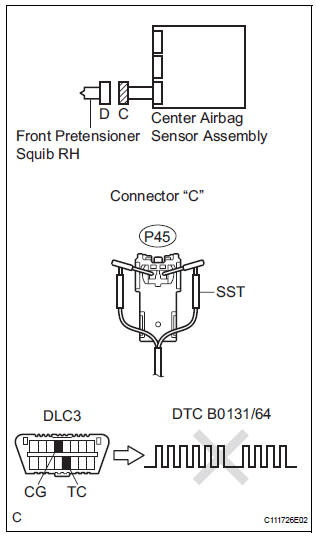
- Turn the ignition switch to the LOCK position.
- Disconnect the negative (-) terminal cable from the battery, and wait for at least 90 seconds.
- Disconnect the connectors from the front seat outer belt assembly RH.
- Connect the white wire side of SST (resistance 2.1 Ω) to the floor wire No. 2.
CAUTION: Never connect a tester to the front seat outer belt assembly RH (front pretensioner squib RH) for measurement, as this may lead to a serious injury due to airbag deployment.
NOTICE: Do not forcibly insert the SST into the terminals of the connector when connecting.
Insert the SST straight into the terminals of the connector.
SST 09843-18060
- Connect the negative (-) terminal cable to the battery, and wait for at least 2 seconds.
- Turn the ignition switch to the ON position, and wait for at least 60 seconds.
- Clear the DTCs stored in memory (5).
- Turn the ignition switch to the LOCK position.
- Turn the ignition switch to the ON position, and wait for at least 60 seconds.
- Check the DTCs
OK: DTC B0131/64 is not output. HINT: Codes other than DTC B0131/64 may be output at this time, but they are not related to this check.
 Go to step 2

REPLACE FRONT SEAT OUTER BELT ASSEMBLY RH
2 CHECK FLOOR WIRE NO.2 (FRONT PRETENSIONER SQUIB RH CIRCUIT)
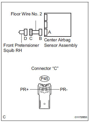
- Turn the ignition switch to the LOCK position.
- Disconnect the negative (-) terminal cable from the battery, and wait for at least 90 seconds.
- Disconnect the SST (resistance 2.1 Ω) from the floor wire No. 2.
- Disconnect the connector from the center airbag sensor assembly.
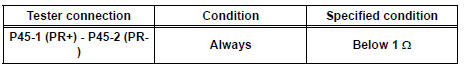
- Measure the resistance according to the value(s) in the table below.
Standard resistance
 REPAIR OR REPLACE FLOOR WIRE
NO.2
REPAIR OR REPLACE FLOOR WIRE
NO.2

3 CHECK CENTER AIRBAG SENSOR ASSEMBLY
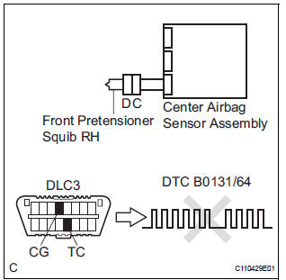
- Connect the connectors to the front seat outer belt assembly RH and the center airbag sensor assembly.
- Connect the negative (-) terminal cable to the battery, and wait for at least 2 seconds.
- Turn the ignition switch to the ON position, and wait for at least 60 seconds.
- Clear the DTCs stored in memory (5).
- Turn the ignition switch to the LOCK position.
- Turn the ignition switch to the ON position, and wait for at least 60 seconds.
- Check the DTCs (5).
OK: DTC B0131/64 is not output. HINT: Codes other than code B0131/64 may be output at this time, but they are not related to this check.
 REPLACE CENTER AIRBAG SENSOR
ASSEMBLY
REPLACE CENTER AIRBAG SENSOR
ASSEMBLY

USE SIMULATION METHOD TO CHECK
 Short in Front Pretensioner Squib RH Circuit
DTC B0130/63 Short in Front Pretensioner Squib RH Circuit
DESCRIPTION
The front pretensioner squib RH circuit consists of the center airbag sensor
assembly and the front seat
outer belt assembly ...
 Short to GND in Front Pretensioner Squib RH
Circuit
Short to GND in Front Pretensioner Squib RH
Circuit
DTC B0132/61 Short to GND in Front Pretensioner Squib RH
Circuit
DESCRIPTION
The front pretensioner squib RH circuit consists of the center airbag sensor
assembly and the front seat
outer belt a ...
Other materials:
Problem symptoms table
HINT:
Before inspecting the suspected areas listed in the table
below, check the fuse and relay.
Before inspecting the suspected areas listed in the table
below, check the DTCs.
Methods used to verify the cause of the problem are listed
in order of probability in the ...
Oxygen (A/F) Sensor Heater Control Circuit
HINT
Although the DTC titles say the oxygen sensor, these DTCs relate to the
Air-Fuel Ratio (A/F) sensor.
Sensor 1 refers to the sensor mounted in front of the Three-Way
Catalytic Converter (TWC) and
located near the engine assembly.
DESCRIPTION
Refer to DTC P2195 (See page ES- ...
Removal
1. REMOVE REAR DOOR SCUFF PLATE LH
2. REMOVE REAR DOOR WEATHERSTRIP LH
3. REMOVE BACK DOOR WEATHERSTRIP
4. REMOVE BACK DOOR SCUFF PLATE
5. REMOVE QUARTER TRIM FRONT PANEL ASSEMBLY LH
6. REMOVE POWER POINT SOCKET ASSEMBLY
Release the 2 claw fittings and remove the power
point soc ...
