Toyota Sienna Service Manual: Open in Occupant Classification ECU Battery Positive Line
DTC B1794 Open in Occupant Classification ECU Battery Positive Line
DESCRIPTION
This circuit consists of the occupant classification ECU and the power source circuit (battery, fuse, wire harness).
DTC B1794 is recorded when a malfunction is detected in the occupant classification ECU or the power source circuit.
HINT: When DTC B1794 is output after switching the ignition switch LOCK-ON-LOCK 50 times in a row when a malfunction occurs in the power circuit for the occupant classification system, the DTC is output again when a malfunction is detected even once after being cleared, unless the normal system code is
|
DTC No. |
DTC Detecting Condition |
Trouble Area |
|
B1794 |
|
|
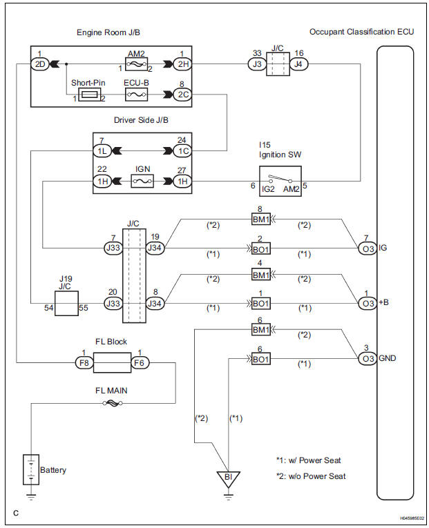
WIRING DIAGRAM
INSPECTION PROCEDURE
1 CHECK BATTERY
- Measure the voltage of the battery.
Standard: 11 to 14 V
2 CHECK FUSE
- Check the ECU-B fuse.
Standard: Below 1 Ω
3 CHECK WIRE HARNESS
- Turn the ignition switch to the LOCK position.
- Disconnect the negative (-) terminal cable from the battery, and wait for at least 90 seconds.
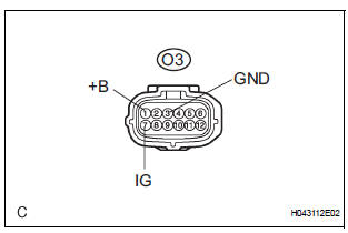
- Disconnect the connector from the occupant classification ECU.
- Connect the negative (-) terminal cable to the battery.
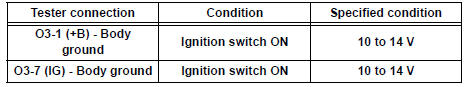
- Turn the ignition switch to the ON position.
- Measure the voltage and resistance according to the value(s) in the table below.
Standard voltage
- Turn the ignition switch to the LOCK position.
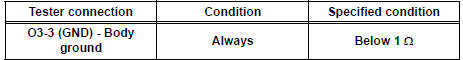
- Measure the resistance and resistance according to the value(s) in the table below.
Standard resistance
4 CHECK DTC
- Turn the ignition switch to the ON position.
(b) Clear the DTCs stored in memory (35).
HINT: First clear DTCs stored in the occupant classification ECU and then in the center airbag sensor assembly.
- Turn the ignition switch to the LOCK position.
- Turn the ignition switch to the ON position, and wait for at least 10 seconds.
- Using the intelligent tester, check the DTCs of the occupant classification ECU (35).
OK: DTC B1794 is not output. HINT: Codes other than code B1794 may be output at this time, but they are not related to this check.
USE SIMULATION METHOD TO CHECK
5 REPLACE OCCUPANT CLASSIFICATION ECU
- Turn the ignition switch to the LOCK position.
- Disconnect the negative (-) terminal cable from the battery, and wait for at least 90 seconds.
- Replace the occupant classification ECU
6 PERFORM ZERO POINT CALIBRATION
- Connect the negative (-) terminal cable to the battery.
- Connect the intelligent tester to the DLC3.
- Turn the ignition switch to the ON position.
- Using the intelligent tester, perform the "Zero point calibration" (28).
OK: The "COMPLETED" is displayed.
7 PERFORM SENSITIVITY CHECK
- Using the intelligent tester, perform the "Sensitivity check"
Standard value: 27 to 33 kg (59.52 to 72.75 lb)
END
 Occupant Classification Sensor Power Supply
Circuit Malfunction
Occupant Classification Sensor Power Supply
Circuit Malfunction
DTC B1793 Occupant Classification Sensor Power Supply
Circuit Malfunction
DESCRIPTION
The occupant classification sensor power supply circuit consists of the
occupant classification ECU and
the ...
 Occupant Classification ECU Malfunction
DTC B1795 Occupant Classification ECU Malfunction
DESCRIPTION
DTC B1795 is recorded when a malfunction is detected in the occupant
classification ECU.
Troubleshoot DTC B1771 first when the DTCs ...
Other materials:
Terminals of ECU
1. CHECK INSTRUMENT PANEL J/B ASSEMBLY
(MULTIPLEX NETWORK BODY ECU)
Disconnect the B6, B7 and B9 ECU connectors.
Disconnect the 1A, 1C, 1L and 1K J/B connectors.
Measure the voltage and resistance between each
terminal of the wire harness side connectors and
body gro ...
Inspection
1. INSPECT WINDSHIELD WIPER MOTOR ASSEMBLY
LO Operation Check
Connect the battery (+) to the terminal 1 (+1) of
the connector, the battery (-) to the terminal 5
(E) of the connector, and check that the motor
operates at low speed (LO).
HI Operation Check
...
Installation
1. INSTALL OUTSIDE MOULDING
Using a heat light, heat the mounting surface of the
vehicle body between 40 to 60 C (104 to 140 F).
NOTICE:
Do not heat the body excessively.
Remove the tape from the vehicle body.
Wipe off the stains with cleaner.
Clean the outside moulding (if reusing t ...
