Toyota Sienna Service Manual: Open in Side Squib LH Circuit
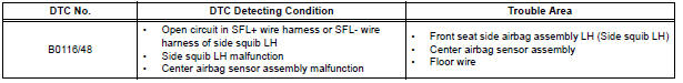
DTC B0116/48 Open in Side Squib LH Circuit
DESCRIPTION
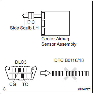
The side squib LH circuit consists of the center airbag sensor assembly and the front seat side assembly LH.
This circuit instructs the SRS to deploy when deployment conditions are met.
DTC B0116/48 is recorded when an open circuit is detected in the side squib LH circuit.
WIRING DIAGRAM
INSPECTION PROCEDURE
HINT:
- Perform the simulation method by selecting the "check mode" (signal check) with the intelligent tester.
- After selecting the "check mode" (signal check), perform the simulation method by wiggling each connector of the airbag system or driving the vehicle on a city or rough road
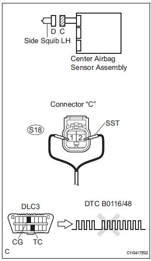
1 CHECK FRONT SEAT SIDE AIRBAG ASSEMBLY LH (SIDE SQUIB LH)
- Turn the ignition switch to the LOCK position.
- Disconnect the negative (-) terminal cable from the battery, and wait for at least 90 seconds.
- Disconnect the connectors from the front seat side airbag assembly LH.
- Connect the black wire side of SST (resistance 2.1 Ω) to the floor wire.
CAUTION: Never connect a tester to the front seat side airbag assembly LH (side squib LH) for measurement, as this may lead to a serious injury due to airbag deployment.
NOTICE: Do not forcibly insert the SST into the terminals of the connector when connecting.
Insert the SST straight into the terminals of the connector.
SST 09843-18060
- Connect the negative (-) terminal cable to the battery, and wait for at least 2 seconds.
- Turn the ignition switch to the ON position, and wait for at least 60 seconds.
- Clear the DTCs stored in memory.
- Turn the ignition switch to the LOCK position.
- Turn the ignition switch to the ON position, and wait for at least 60 seconds.
- Check the DTCs
OK: DTC B0116/48 is not output.
HINT: Codes other than DTC B0116/48 may be output at this time, but they are not related to this check.
REPLACE FRONT SEAT ASSEMBLY LH
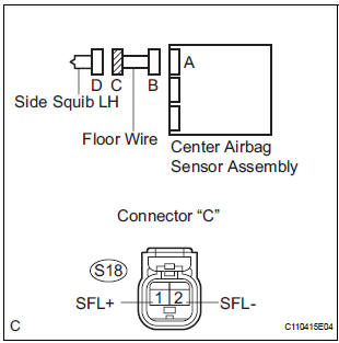
2 CHECK FLOOR WIRE (SIDE SQUIB LH CIRCUIT)
- Turn the ignition switch to the LOCK position.
- Disconnect the negative (-) terminal cable from the battery, and wait for at least 90 seconds.
- Disconnect the SST (resistance 2.1 Ω) from the floor wire.
- Disconnect the connector from the center airbag sensor assembly.
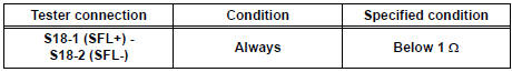
- Measure the resistance according to the value(s) in the table below.
Standard resistance
3 CHECK CENTER AIRBAG SENSOR ASSEMBLY
- Connect the connectors to the front seat side airbag assembly LH and the center airbag sensor assembly.
- Connect the negative (-) terminal cable to the battery, and wait for at least 2 seconds.
- Turn the ignition switch to the ON position, and wait for at least 60 seconds.
- Clear the DTCs stored in memory.
- Turn the ignition switch to the LOCK position.
- Turn the ignition switch to the ON position, and wait for at least 60 seconds.
- Check the DTCs.
OK: DTC B0116/48 is not output.
HINT: Codes other than code B0116/48 may be output at this time, but they are not related to this check.
USE SIMULATION METHOD TO CHECK
 Short in Side Squib LH Circuit
DTC B0115/47 Short in Side Squib LH Circuit
DESCRIPTION
The side squib LH circuit consists of the center airbag sensor assembly and
the front seat side airbag
assembly LH.
This circuit instruc ...
 Short to GND in Side Squib LH Circuit
DTC B0117/45 Short to GND in Side Squib LH Circuit
DESCRIPTION
The side squib LH circuit consists of the center airbag sensor assembly and
the front seat side airbag
assembly LH.
This circuit ...
Other materials:
Short to GND in Rear Curtain Shield Squib RH
Circuit
DTC B1632/81 Short to GND in Rear Curtain Shield Squib RH
Circuit
DESCRIPTION
The rear curtain shield squib RH circuit consists of the center airbag sensor
assembly and the curtain
shield airbag assembly RH.
The circuit instructs the SRS to deploy when deployment conditions are met.
DTC ...
Terminals of ECU
1. CHECK INSTRUMENT PANEL J/B ASSEMBLY
(MULTIPLEX NETWORK BODY ECU)
Disconnect the B6, B7 and B9 ECU connectors.
Disconnect the 1A, 1C, 1L and 1K J/B connectors.
Measure the voltage and resistance between each
terminal of the wire harness side connectors and
body gro ...
Voice settings
This screen is used for guidance for voice command systems
setting.
Adjust the voice guidance volume
setting.
Set the voice recognition
prompts ÔÇťHighÔÇŁ, ÔÇťLowÔÇŁ or ÔÇťOffÔÇŁ.
Set the train voice recognition.
Set the voice prompt interrupt
on/off.
Set the voice recognition ...
