Toyota Sienna Service Manual: Oxygen Sensor Heater Control Circuit Low/ Oxygen Sensor Heater Control Circuit High/ Oxygen Sensor Heater Circuit Malfunction
DTC P0037 Oxygen Sensor Heater Control Circuit Low (Bank 1 Sensor 2)
DTC P0038 Oxygen Sensor Heater Control Circuit High (Bank 1 Sensor 2)
DTC P0057 Oxygen Sensor Heater Control Circuit Low (Bank 2 Sensor 2)
DTC P0058 Oxygen Sensor Heater Control Circuit High (Bank 2 Sensor 2)
DTC P0141 Oxygen Sensor Heater Circuit Malfunction (Bank 1 Sensor 2)
DTC P0161 Oxygen Sensor Heater Circuit Malfunction (Bank 2 Sensor 2)
HINT: Sensor 2 refers to the sensor mounted behind the Three-Way Catalytic Converter (TWC) and located furthest from the engine assembly.
DESCRIPTION
Refer to DTC P0136.
HINT: When any of these DTCs are set, the ECM enters fail-safe mode. The ECM turns off the Heated Oxygen (HO2) sensor heater in fail-safe mode. Fail-safe mode continues until the ignition switch is turned off.
|
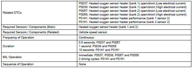
DTC No. |
DTC Detection Condition |
Trouble Area |
| P0037 P0057 |
Heated Oxygen (HO2) sensor heater current is less than 0.3 A (1 trip detection logic) |
|
| P0038 P0058 |
Heated Oxygen (HO2) sensor heater current is more than 2 A (1 trip detection logic) |
|
| P0141 P0161 |
Cumulative heater resistance correction value exceeds the acceptable threshold (2 trip detection logic) |
|
HINT:
- Bank 1 refers to the bank that includes cylinder No. 1.
- Bank 2 refers to the bank that does not include cylinder No. 1.
- Sensor 1 refers to the sensor closest to the engine assembly.
- Sensor 2 refers to the sensor furthest away from the engine assembly.
MONITOR DESCRIPTION
The sensing position of the Heated Oxygen (HO2) sensor has a zirconia element which is used to detect the oxygen concentration in the exhaust gas. If the zirconia element is at the appropriate temperature, and the difference between the oxygen concentrations surrounding the inside and outside surfaces of the sensor is large, the zirconia element generates voltage signals. In order to increase the oxygen concentration detecting capacity of the zirconia element, the ECM supplements the heat from the exhaust with heat from a heating element inside the sensor.
Heated oxygen sensor heater range check (P0037, P0038, P0057 and P0058): The ECM monitors the current applied to the O2 sensor heater to check the heater for malfunctions. If the current is below the threshold value, the ECM will determine that there is an open circuit in the heater. If the current is above the threshold value, the ECM will determine that there is a short circuit in the heater.
Example: The ECM sets DTC P0038 or P0058 when the current in the HO2 sensor heater is more than 2 A.
Conversely, when the heater current is less than 0.3 A, DTC P0037 or P0057 is set.
Heated oxygen sensor heater performance (P0141 and P0161): After the accumulated heater ON time exceeds 100 seconds, the ECM calculates the heater resistance using the battery voltage and the current applied to the heater. If the resistance is above the threshold value, the ECM will determine that there is a malfunction in the HO2S heater and set DTC P0141 and P0161.
MONITOR STRATEGY
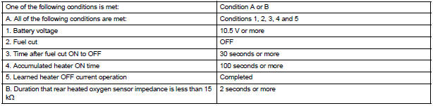
TYPICAL ENABLING CONDITIONS
All:

P0037 and P0057:

P0038 and P0058 Case 1:

P0038 and P0058 Case 2:

P0141 and P0161:
TYPICAL MALFUNCTION THRESHOLDS
P0037 and P0057:

P0038 and P0058:

P0141 and P0161 (Heater performance monitor check):

COMPONENT OPERATING RANGE

MONITOR RESULT
Refer to CHECKING MONITOR STATUS.
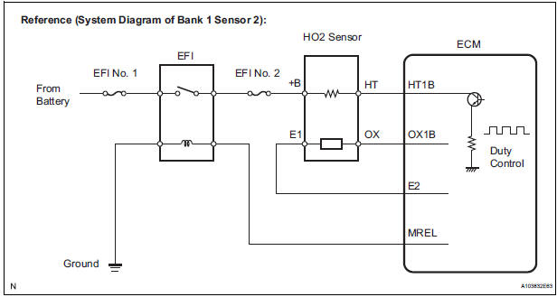
WIRING DIAGRAM
Refer to DTC P0136.
INSPECTION PROCEDURE
HINT:
- If other DTCs relating to different systems that have terminal E2 as the ground terminal are output simultaneously, terminal E2 may have an open circuit.
- Read freeze frame data using the intelligent tester. The ECM records vehicle and driving condition information as freeze frame data the moment a DTC is stored. When troubleshooting, freeze frame data can be helpful in determining whether the vehicle was running or stopped, whether the engine was warmed up or not, whether the air-fuel ratio was lean or rich, as well as other data recorded at the time of a malfunction.
1 INSPECT HEATED OXYGEN SENSOR (HEATER RESISTANCE)
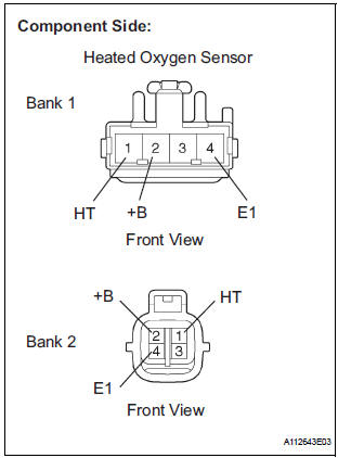
- Disconnect the H14 heated oxygen (HO2) sensor connector (Bank 1 Sensor 2) or H9 heated oxygen sensor connector (Bank 2 Sensor 2).
- Measure the resistance according to the value(s) in the table below.
Standard resistance: Bank 1
Bank 2
- Reconnect the HO2 sensor connectors.
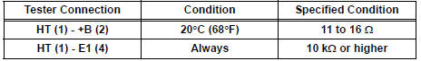
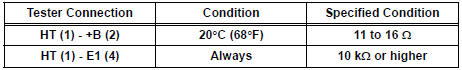
2 CHECK TERMINAL VOLTAGE (+B OF SENSOR)
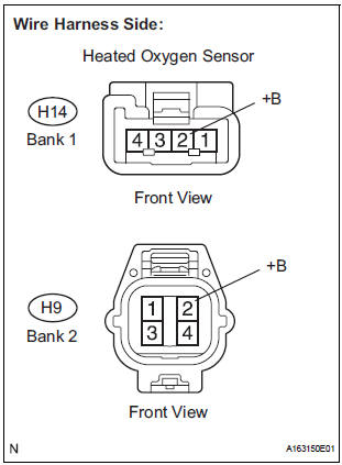
- Disconnect the H14 or H9 HO2 sensor connector.
- Turn the ignition switch to the ON position.
- Measure the voltage according to the value(s) in the table below.
Standard voltage
- Reconnect the HO2 sensor connector
3 INSPECT FUSE (EFI NO. 2 FUSE)
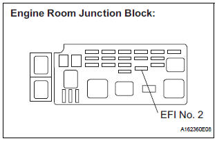
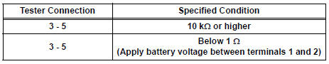
- Remove the EFI No. 2 fuse from the engine room junction block.
- Measure the resistance according to the value(s) in the
table below.
Standard resistance: Below 1 Ω
- Reinstall the EFI No. 2 fuse
4 INSPECT RELAY (EFI RELAY)
- Remove the EFI relay from the engine room junction block.
- Measure the resistance according to the value(s) in the table below.
Standard resistance
- Reinstall the EFI relay.
REPAIR OR REPLACE HARNESS OR CONNECTOR (HO2 SENSOR - EFI RELAY)
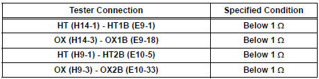
5 CHECK HARNESS AND CONNECTOR (HO2 SENSOR - ECM)
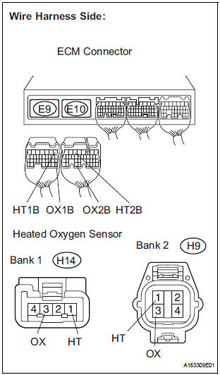
- Disconnect the H14 or H9 HO2 sensor connector.
- Disconnect the E9 and E10 ECM connectors.
- Measure the resistance according to the value(s) in the table below.
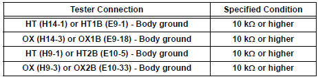
Standard resistance: Check for open
Check for short
- Reconnect the ECM connectors.
- Reconnect the HO2 sensor connectors.
6 CHECK WHETHER DTC OUTPUT RECURS
- Connect the intelligent tester to the DLC3.
- Turn the ignition switch to the ON position.
- Turn the intelligent tester ON.
- Clear the DTCs.
- Start the engine.
- Allow the engine to idle for 1 minute or more.
- Select the following menu items: DIAGNOSIS / ENHANCED OBD II / DTC INFO / CURRENT CODES.
- Read the DTCs.
Result

CHECK FOR INTERMITTENT PROBLEMS
 Oxygen (A/F) Sensor Heater Control Circuit
Low/ Oxygen (A/F) Sensor Heater Control Circuit
High
Oxygen (A/F) Sensor Heater Control Circuit
Low/ Oxygen (A/F) Sensor Heater Control Circuit
High
DTC P0031 Oxygen (A/F) Sensor Heater Control Circuit
Low (Bank 1 Sensor 1)
DTC P0032 Oxygen (A/F) Sensor Heater Control Circuit
High (Bank 1 Sensor 1)
DTC P0051 Oxygen (A/F) Sensor Heater Control ...
 Mass or Volume Air Flow Circuit/ Mass or Volume Air Flow Circuit Low Input/
Mass or Volume Air Flow Circuit High Input
Mass or Volume Air Flow Circuit/ Mass or Volume Air Flow Circuit Low Input/
Mass or Volume Air Flow Circuit High Input
DESCRIPTION
The Mass Air Flow (MAF) meter is a sensor that measures the amount of air
flowing through the throttle
valve. The ECM uses this information to determine the fuel injection time and to ...
Other materials:
Removal
1. REMOVE INSTRUMENT CLUSTER CENTER NO. 1 FINISH PANEL
2. REMOVE INSTRUMENT CLUSTER CENTER NO. 2 FINISH PANEL
3. REMOVE INSTRUMENT CLUSTER FINISH PANEL GARNISH
4. REMOVE RADIO RECEIVER
Remove the 4 screws.
Disconnect the connectors and remove the radio
receiver with bracke ...
Radio Receiver Power Source Circuit
DESCRIPTION
This circuit provides power to the radio receiver.
WIRING DIAGRAM
INSPECTION PROCEDURE
1 INSPECT RADIO RECEIVER ASSEMBLY
Disconnect the radio receiver connector.
Measure the resistance according to the value in the
table below.
Standard resistance
Measure t ...
Installation
1. INSTALL REAR DRIVE SHAFT ASSEMBLY LH
(a) Install the drive shaft to the axle carrier.
NOTICE:
Be careful not to damage the boot and ABS
speed sensor rotor to the drive shaft and oil seal
of the axle hub bearing.
(b) Align the matchmarks and connect the drive shaft to
the side gear shaf ...
