Toyota Sienna Service Manual: Passenger Airbag ON/OFF Indicator Circuit Malfunction
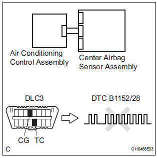
DTC B1152/28 Passenger Airbag ON/OFF Indicator Circuit Malfunction
DESCRIPTION
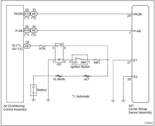
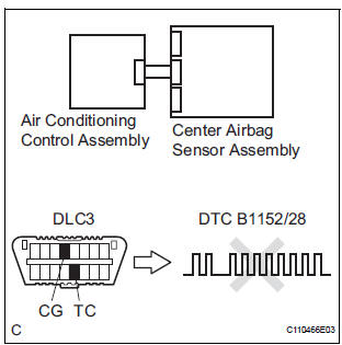
The passenger airbag ON/OFF indicator circuit consists of the center airbag sensor assembly and passenger airbag ON/OFF indicator.
This circuit indicates the operation condition of the front passenger airbag, the front seat side airbag RH and front seat belt pretensioner RH.
DTC B1152/28 is recorded when a malfunction is detected in the passenger airbag ON/OFF indicator circuit.
|
DTC No. |
DTC Detecting Condition |
Trouble Area |
|
B1152/28 |
|
|
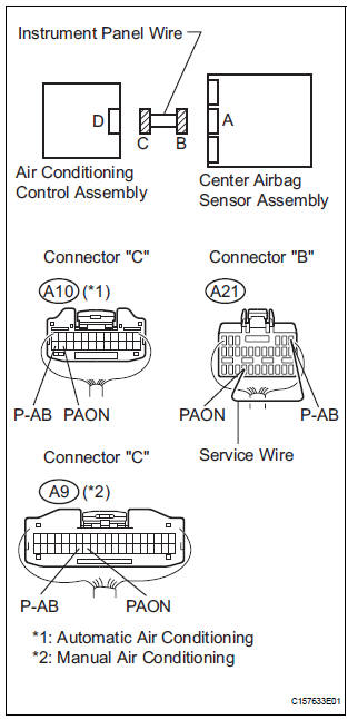
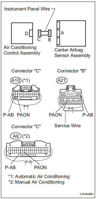
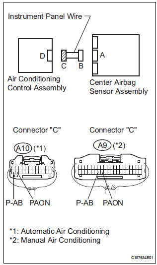
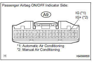
WIRING DIAGRAM
INSPECTION PROCEDURE
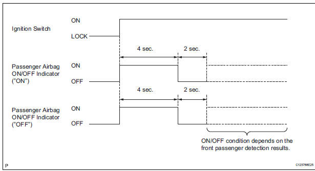
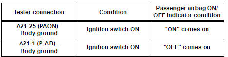
1 CHECK PASSENGER AIRBAG ON/OFF INDICATOR OPERATION
- Turn the ignition switch to the ON position.
- Check the passenger airbag ON/OFF indicator operation.
HINT: Refer to the normal condition of the passenger airbag ON/OFF indicator (
Result

 Go to step 10

2 CHECK CONNECTION OF CONNECTORS
- Turn the ignition switch to the LOCK position.
- Disconnect the negative (-) terminal cable from the battery, and wait for at least 90 seconds.
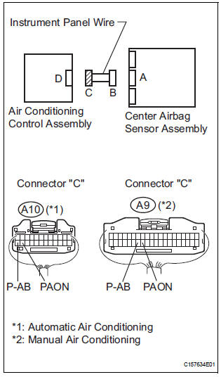
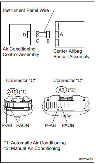
- Check that the connectors are properly connected to the center airbag sensor assembly and the air conditioning control assembly.
OK: The connectors are connected.
 CONNECT CONNECTORS

3 CHECK CONNECTORS
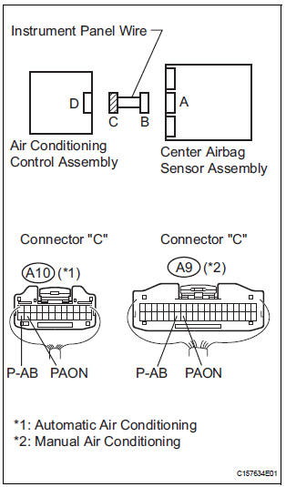
- Disconnect the connectors from the center airbag sensor assembly and the air conditioning control assembly.
- Check that the connectors (on the center airbag sensor assembly side and the air conditioning control assembly side) are not damaged.
OK: The connectors are not deformed or damaged.
 REPAIR OR REPLACE INSTRUMENT
PANEL
WIRE
REPAIR OR REPLACE INSTRUMENT
PANEL
WIRE

4 CHECK PASSENGER AIRBAG ON/OFF INDICATOR
- Connect the connector to the center airbag sensor assembly.
- Connect the negative (-) terminal cable to the battery, and wait for at least 2 seconds.
- Turn the ignition switch to the ON position.
- Check the passenger airbag ON/OFF indicator operation.
OK: The passenger airbag ON/OFF indicator ("ON" and "OFF") does not come on.
 Go to step 6

5 CHECK CENTER AIRBAG SENSOR ASSEMBLY
- Turn the ignition switch to the LOCK position.
- Disconnect the negative (-) terminal cable from the battery, and wait for at least 90 seconds.
- Connect the connector to the air conditioning control assembly.
- Connect the negative (-) terminal cable to the battery, and wait for at least 2 seconds.
- Turn the ignition switch to the ON position, and wait for at least 60 seconds.
- Clear the DTCs stored in memory (5).
- Turn the ignition switch to the LOCK position.
- Turn the ignition switch to the ON position, and wait for at least 60 seconds.
- Check the DTCs (5).
OK: DTC B1152/28 is not output.
HINT: Codes other than code B1152/28 may be output at this time, but they are not related to this check.
 REPLACE CENTER AIRBAG SENSOR
ASSEMBLY
REPLACE CENTER AIRBAG SENSOR
ASSEMBLY

USE SIMULATION METHOD TO CHECK
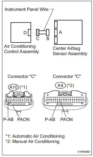
6 CHECK INSTRUMENT PANEL WIRE (OPEN)
- Turn the ignition switch to the LOCK position.
- Disconnect the negative (-) terminal cable from the battery, and wait for at least 90 seconds.
- Disconnect the connector from the center airbag sensor assembly.
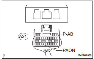
- Using a service wire, connect A21-1 (P-AB) and A21-25
(PAON) of connector "B".
NOTICE: Do not forcibly insert a service wire into the terminals of the connector when connecting.
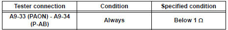
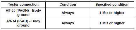
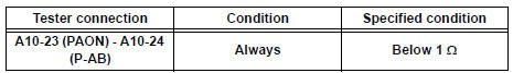
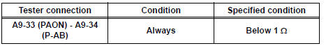
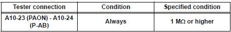
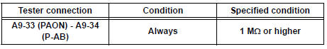
- Measure the resistance according to the value(s) in the table below.
Automatic air conditioning: Standard resistance
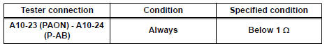
Manual air conditioning: Standard resistance
 REPAIR OR REPLACE INSTRUMENT
PANEL
WIRE
REPAIR OR REPLACE INSTRUMENT
PANEL
WIRE

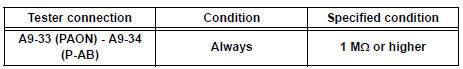
7 CHECK INSTRUMENT PANEL WIRE (SHORT)
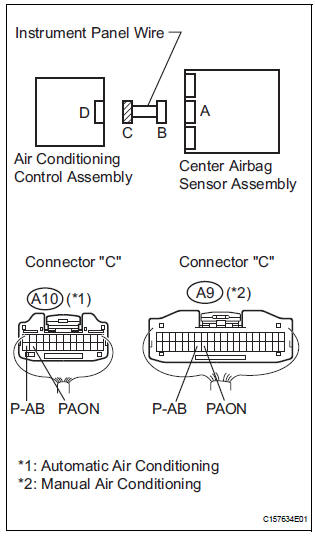
- Disconnect the service wire from connector "B".
- Measure the resistance according to the value(s) in the table below.
Automatic air conditioning: Standard resistance
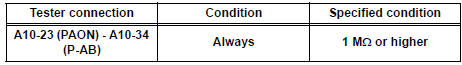
Manual air conditioning: Standard resistance
 REPAIR OR REPLACE INSTRUMENT
PANEL
WIRE
REPAIR OR REPLACE INSTRUMENT
PANEL
WIRE

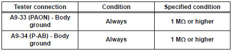
8 CHECK INSTRUMENT PANEL WIRE (SHORT TO GROUND)
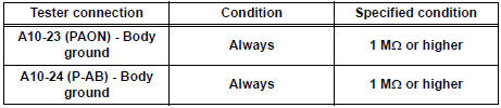
- Measure the resistance according to the value(s) in the table below.
Automatic air conditioning: Standard resistance
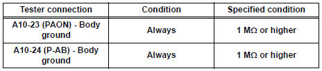
Manual air conditioning: Standard resistance
 REPAIR OR REPLACE INSTRUMENT
PANEL
WIRE
REPAIR OR REPLACE INSTRUMENT
PANEL
WIRE

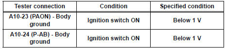
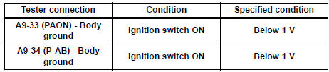
9 CHECK INSTRUMENT PANEL WIRE (SHORT TO B+)
- Connect the negative (-) terminal cable to the battery, and wait for at least 2 seconds.
- Turn the ignition switch to the ON position.
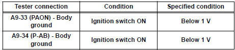
- Measure the voltage according to the value(s) in the table below.
Automatic air conditioning: Standard voltage
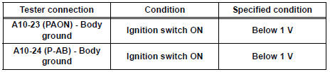
Manual air conditioning: Standard voltage
 REPAIR OR REPLACE INSTRUMENT
PANEL
WIRE
REPAIR OR REPLACE INSTRUMENT
PANEL
WIRE

REPLACE AIR CONDITIONING CONTROL ASSEMBLY
10 CHECK CONNECTION OF CONNECTORS
- Turn the ignition switch to the LOCK position.
- Disconnect the negative (-) terminal cable from the battery, and wait for at least 90 seconds.
- Check that the connectors are properly connected to the center airbag sensor assembly and the air conditioning control assembly.
OK: The connectors are connected.
 CONNECT CONNECTORS

11 CHECK CONNECTORS
- Disconnect the connectors from the center airbag sensor assembly and the air conditioning control assembly.
- Check that the connectors (on the center airbag sensor assembly side and the air conditioning control assembly side) are not damaged.
OK: The connectors are not deformed or damaged.
 REPAIR OR REPLACE INSTRUMENT
PANEL
WIRE
REPAIR OR REPLACE INSTRUMENT
PANEL
WIRE

12 CHECK INSTRUMENT PANEL WIRE (OPEN)
- Using a service wire, connect A21-1 (ABON) and A21-25 (ABOF) of connector "B".
- Measure the resistance according to the value(s) in the table below.
Automatic air conditioning: Standard resistance
Manual air conditioning: Standard resistance
 REPAIR OR REPLACE INSTRUMENT
PANEL
WIRE
REPAIR OR REPLACE INSTRUMENT
PANEL
WIRE

13 CHECK INSTRUMENT PANEL WIRE (SHORT)
- Disconnect the service wire from connector "B".
- Measure the resistance according to the value(s) in the table below.
Automatic air conditioning: Standard resistance
Manual air conditioning: Standard resistance
 REPAIR OR REPLACE INSTRUMENT
PANEL
WIRE
REPAIR OR REPLACE INSTRUMENT
PANEL
WIRE

14 CHECK INSTRUMENT PANEL WIRE (SHORT TO GROUND)
- Measure the resistance according to the value(s) in the table below.
Automatic air conditioning: Standard resistance
Manual air conditioning: Standard resistance
 REPAIR OR REPLACE INSTRUMENT
PANEL
WIRE
REPAIR OR REPLACE INSTRUMENT
PANEL
WIRE

15 CHECK INSTRUMENT PANEL WIRE (SHORT TO B+)
- Connect the negative (-) terminal cable to the battery, and wait for at least 2 seconds.
- Turn the ignition switch to the ON position.
- Measure the voltage according to the value(s) in the table below.
Automatic air conditioning: Standard voltage
Manual air conditioning: Standard voltage
 REPAIR OR REPLACE INSTRUMENT
PANEL
WIRE
REPAIR OR REPLACE INSTRUMENT
PANEL
WIRE

16 CHECK WIRE HARNESS (POWER SOURCE)
- Turn the ignition switch to the LOCK position.
- Disconnect the negative (-) terminal cable from the battery, and wait for at least 90 seconds.
- Connect the connector to the center airbag sensor assembly.
- Turn the ignition switch to the ON position.
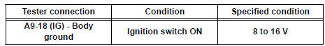
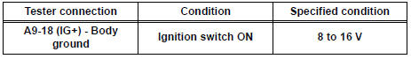
- Measure the voltage and resistance according to the value(s) in the table below.
Automatic air conditioning: Standard voltage
Manual air conditioning: Standard voltage
 REPAIR OR REPLACE POWER
SOURCE
CIRCUIT
REPAIR OR REPLACE POWER
SOURCE
CIRCUIT

17 CHECK PASSENGER AIRBAG ON/OFF INDICATOR
- Turn the ignition switch to the LOCK position.
- Disconnect the negative (-) terminal cable from the battery, and wait for at least 90 seconds.
- Connect the connector to the air conditioning control assembly.
- Disconnect the connector from center airbag sensor assembly.
- Connect the negative (-) terminal cable to the battery, and wait for at least 2 seconds.
- Turn the ignition switch to the ON position.
- Check the passenger airbag ON/OFF indicator condition.
Result
REPLACE AIR CONDITIONING
CONTROL
ASSEMBLY

18 CHECK CENTER AIRBAG SENSOR ASSEMBLY
- Turn the ignition switch to the LOCK position.
- Disconnect the negative (-) terminal cable from the battery, and wait for at least 90 seconds.
- Connect the connector to the center airbag sensor assembly.
- Connect the negative (-) terminal cable to the battery, and wait for at least 2 seconds.
- Turn the ignition switch to the ON position, and wait for at least 60 seconds.
- Clear the DTCs stored in memory (5).
- Turn the ignition switch to the LOCK position.
- Turn the ignition switch to the ON position, and wait for at least 60 seconds.
- Check the DTCs (5).
OK: DTC B1152/28 is not output.
HINT: Codes other than code B1152/28 may be output at this time, but they are not related to this check.
 REPLACE CENTER AIRBAG SENSOR
ASSEMBLY
REPLACE CENTER AIRBAG SENSOR
ASSEMBLY

USE SIMULATION METHOD TO CHECK
 Occupant Classification System Malfunction
DTC B1150/23 Occupant Classification System Malfunction
DESCRIPTION
The occupant classification system circuit consists of the center airbag
sensor assembly and the occupant
classification ECU.
...
 Seat Position Airbag Sensor Circuit Malfunction
DTC B1153/25 Seat Position Airbag Sensor Circuit Malfunction
DESCRIPTION
The seat position airbag sensor circuit consists of the center airbag sensor
assembly and the seat
position airbag sensor. ...
Other materials:
Removal
1. DISCONNECT BATTERY NEGATIVE TERMINAL
2. REMOVE FRONT DOOR SCUFF PLATE LH
HINT:
(See page IP-6)
3. REMOVE FRONT DOOR SCUFF PLATE RH
HINT:
(See page IP-6)
4. REMOVE COWL SIDE TRIM BOARD LH
HINT:
(See page IP-6)
5. REMOVE COWL SIDE TRIM BOARD RH
HINT:
(See page IP-6)
6. REMOVE INSTRUMEN ...
Diagnostic trouble code chart
1. DTCS FOR AIRBAG SYSTEM
If a malfunction code is displayed during the DTC check,
check the circuit listed for the code in the table below
(Proceed to the page listed for that circuit).
HINT:
When the SRS warning light remains on and the DTC
output is the normal system code, a volta ...
Engine Coolant Temperature Circuit Range / Performance Problem
DESCRIPTION
Refer to DTC P0115 (See page ES-133).
MONITOR DESCRIPTION
The ECT sensor is used to monitor the ECT. The ECT sensor has a built-in
thermistor with a resistance
that varies according to the temperature of the engine coolant. When the ECT
becomes low, the
resistance of the ...
