Toyota Sienna Service Manual: Passenger Airbag ON/OFF Indicator Circuit Malfunction
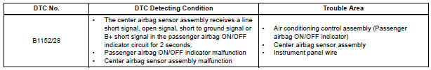
DTC B1152/28 Passenger Airbag ON/OFF Indicator Circuit Malfunction
DESCRIPTION
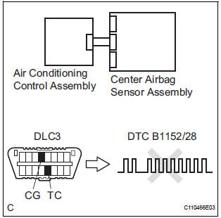
The passenger airbag ON/OFF indicator circuit consists of the center airbag sensor assembly and passenger airbag ON/OFF indicator.
This circuit indicates the operation condition of the front passenger airbag, the front seat side airbag RH and front seat belt pretensioner RH.
DTC B1152/28 is recorded when a malfunction is detected in the passenger airbag ON/OFF indicator circuit.
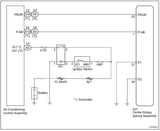
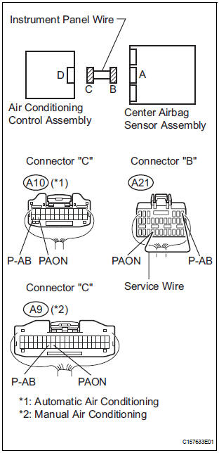
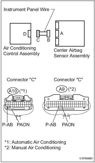
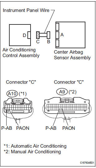
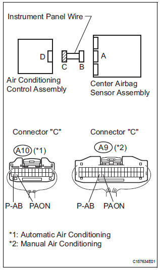
WIRING DIAGRAM
INSPECTION PROCEDURE
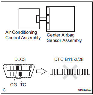
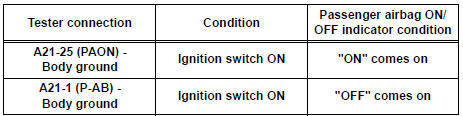
1 CHECK PASSENGER AIRBAG ON/OFF INDICATOR OPERATION
- Turn the ignition switch to the ON position.
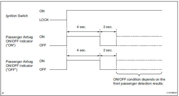
- Check the passenger airbag ON/OFF indicator operation.
HINT: Refer to the normal condition of the passenger airbag ON/OFF indicator
Result

2 CHECK CONNECTION OF CONNECTORS
- Turn the ignition switch to the LOCK position.
- Disconnect the negative (-) terminal cable from the battery, and wait for at least 90 seconds.
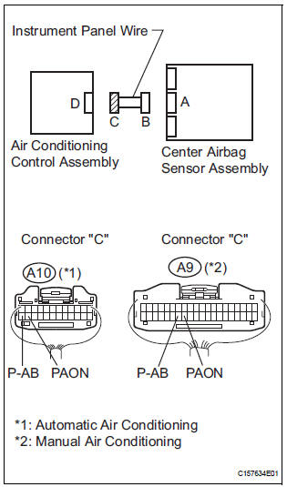
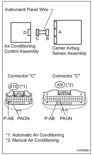
- Check that the connectors are properly connected to the center airbag sensor assembly and the air conditioning control assembly.
OK: The connectors are connected.
3 CHECK CONNECTORS
- Disconnect the connectors from the center airbag sensor assembly and the air conditioning control assembly.
- Check that the connectors (on the center airbag sensor assembly side and the air conditioning control assembly side) are not damaged.
OK: The connectors are not deformed or damaged.
4 CHECK PASSENGER AIRBAG ON/OFF INDICATOR
- Connect the connector to the center airbag sensor assembly.
- Connect the negative (-) terminal cable to the battery, and wait for at least 2 seconds.
- Turn the ignition switch to the ON position.
- Check the passenger airbag ON/OFF indicator operation.
OK: The passenger airbag ON/OFF indicator ("ON" and "OFF") does not come on.
5 CHECK CENTER AIRBAG SENSOR ASSEMBLY
- Turn the ignition switch to the LOCK position.
- Disconnect the negative (-) terminal cable from the battery, and wait for at least 90 seconds.
- Connect the connector to the air conditioning control assembly.
- Connect the negative (-) terminal cable to the battery, and wait for at least 2 seconds.
- Turn the ignition switch to the ON position, and wait for at least 60 seconds.
- Clear the DTCs stored in memory.
- Turn the ignition switch to the LOCK position.
- Turn the ignition switch to the ON position, and wait for at least 60 seconds.
- Check the DTCs.
OK: DTC B1152/28 is not output.
HINT: Codes other than code B1152/28 may be output at this time, but they are not related to this check.
USE SIMULATION METHOD TO CHECK
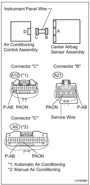
6 CHECK INSTRUMENT PANEL WIRE (OPEN)
- Turn the ignition switch to the LOCK position.
- Disconnect the negative (-) terminal cable from the battery, and wait for at least 90 seconds.
- Disconnect the connector from the center airbag sensor assembly.
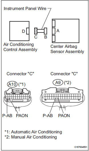
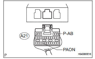
- Using a service wire, connect A21-1 (P-AB) and A21-25
(PAON) of connector "B".
NOTICE: Do not forcibly insert a service wire into the terminals of the connector when connecting.
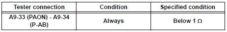
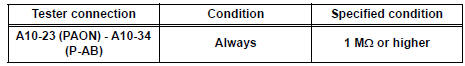
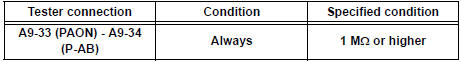
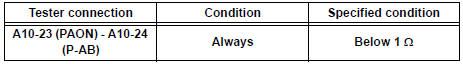
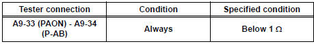
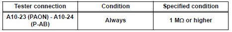
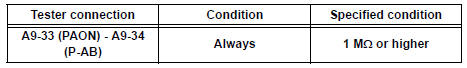
- Measure the resistance according to the value(s) in the table below.
Automatic air conditioning: Standard resistance
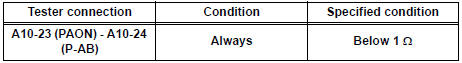
Manual air conditioning: Standard resistance
7 CHECK INSTRUMENT PANEL WIRE (SHORT)
- Disconnect the service wire from connector "B".
- Measure the resistance according to the value(s) in the table below.
Automatic air conditioning: Standard resistance
Manual air conditioning: Standard resistance
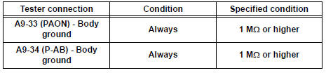
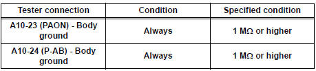
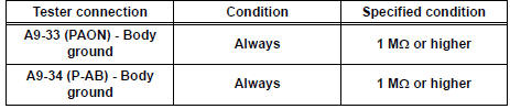
8 CHECK INSTRUMENT PANEL WIRE (SHORT TO GROUND)
- Measure the resistance according to the value(s) in the table below.
Automatic air conditioning: Standard resistance
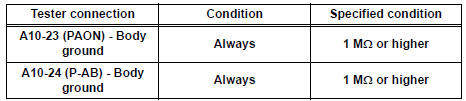
Manual air conditioning: Standard resistance
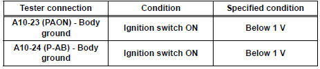
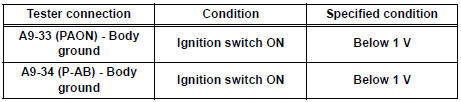
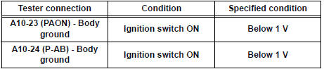
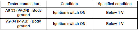
9 CHECK INSTRUMENT PANEL WIRE (SHORT TO B+)
- Connect the negative (-) terminal cable to the battery, and wait for at least 2 seconds.
- Turn the ignition switch to the ON position.
- Measure the voltage according to the value(s) in the table below.
Automatic air conditioning: Standard voltage
Manual air conditioning: Standard voltage
REPLACE AIR CONDITIONING CONTROL ASSEMBLY
10 CHECK CONNECTION OF CONNECTORS
- Turn the ignition switch to the LOCK position.
- Disconnect the negative (-) terminal cable from the battery, and wait for at least 90 seconds.
- Check that the connectors are properly connected to the center airbag sensor assembly and the air conditioning control assembly.
OK: The connectors are connected
11 CHECK CONNECTORS
- Disconnect the connectors from the center airbag sensor assembly and the air conditioning control assembly.
- Check that the connectors (on the center airbag sensor assembly side and the air conditioning control assembly side) are not damaged.
OK: The connectors are not deformed or damaged.
12 CHECK INSTRUMENT PANEL WIRE (OPEN)
- Using a service wire, connect A21-1 (ABON) and A21-25 (ABOF) of connector "B".
- Measure the resistance according to the value(s) in the table below.
Automatic air conditioning: Standard resistance
Manual air conditioning: Standard resistance
13 CHECK INSTRUMENT PANEL WIRE (SHORT)
- Disconnect the service wire from connector "B".
- Measure the resistance according to the value(s) in the table below.
Automatic air conditioning: Standard resistance
Manual air conditioning: Standard resistance
14 CHECK INSTRUMENT PANEL WIRE (SHORT TO GROUND)
- Measure the resistance according to the value(s) in the table below.
Automatic air conditioning: Standard resistance
Manual air conditioning: Standard resistance
15 CHECK INSTRUMENT PANEL WIRE (SHORT TO B+)
- Connect the negative (-) terminal cable to the battery, and wait for at least 2 seconds.
- Turn the ignition switch to the ON position.
- Measure the voltage according to the value(s) in the table below.
Automatic air conditioning: Standard voltage
Manual air conditioning: Standard voltage
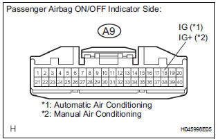
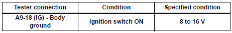
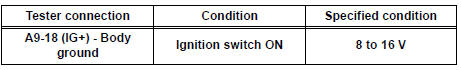
16 CHECK WIRE HARNESS (POWER SOURCE)
- Turn the ignition switch to the LOCK position.
- Disconnect the negative (-) terminal cable from the battery, and wait for at least 90 seconds.
- Connect the connector to the center airbag sensor assembly.
- Turn the ignition switch to the ON position.
- Measure the voltage and resistance according to the value(s) in the table below.
Automatic air conditioning: Standard voltage
Manual air conditioning: Standard voltage
17 CHECK PASSENGER AIRBAG ON/OFF INDICATOR
- Turn the ignition switch to the LOCK position.
- Disconnect the negative (-) terminal cable from the battery, and wait for at least 90 seconds.
- Connect the connector to the air conditioning control assembly.
- Disconnect the connector from center airbag sensor assembly.
- Connect the negative (-) terminal cable to the battery, and wait for at least 2 seconds.
- Turn the ignition switch to the ON position.
- Check the passenger airbag ON/OFF indicator condition.
Result
18 CHECK CENTER AIRBAG SENSOR ASSEMBLY
- Turn the ignition switch to the LOCK position.
- Disconnect the negative (-) terminal cable from the battery, and wait for at least 90 seconds.
- Connect the connector to the center airbag sensor assembly.
- Connect the negative (-) terminal cable to the battery, and wait for at least 2 seconds.
- Turn the ignition switch to the ON position, and wait for at least 60 seconds.
- Clear the DTCs stored in memory.
- Turn the ignition switch to the LOCK position.
- Turn the ignition switch to the ON position, and wait for at least 60 seconds.
- Check the DTCs.
OK: DTC B1152/28 is not output.
HINT: Codes other than code B1152/28 may be output at this time, but they are not related to this check.
USE SIMULATION METHOD TO CHECK
 Occupant Classification System Malfunction
DTC B1150/23 Occupant Classification System Malfunction
DESCRIPTION
The occupant classification system circuit consists of the center airbag
sensor assembly and the occupant
classification ECU.
...
 Seat Position Airbag Sensor Circuit Malfunction
DTC B1153/25 Seat Position Airbag Sensor Circuit Malfunction
DESCRIPTION
The seat position airbag sensor circuit consists of the center airbag sensor
assembly and the seat
position airbag sensor. ...
Other materials:
DSP Error/ DSP Error
DTC 62-78 DSP Error
DTC 63-78 DSP Error
DESCRIPTION
INSPECTION PROCEDURE
HINT:
After the inspection is completed, clear the DTCs.
NOTICE:
These codes may be output even if there is no malfunction.
If these codes are output frequently, replace the radio receiver.
1 CLEA ...
Adjustment
HINT:
On the RH side, use the same procedures as on the LH
side.
Since a centering bolt is used as door hinge mounting
bolts on the body side and the door side, the door cannot
be adjusted with them on. Substitute a bolt with a washer
for the centering bolt.
1. INSPECT BACK DOOR PAN ...
Check mode procedure
HINT:
Check mode has a higher sensitivity to malfunctions and can
detect malfunction that normal mode cannot detect. Check
mode can also detect all the malfunctions that normal mode
can detect. In check mode, DTCs are detected with 1-trip
detection logic.
Dtc check (check mode)
HINT:
I ...
