Toyota Sienna Service Manual: Passenger Side Outer Mirror ECU
DTC B1208 Passenger Side Outer Mirror ECU
DESCRIPTION
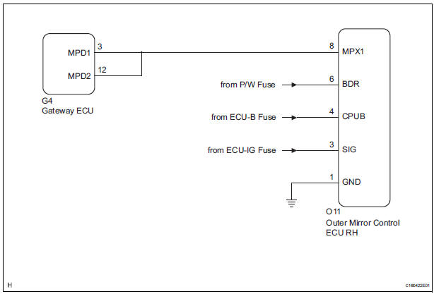
This DTC is detected when communication between the outer mirror control ECU RH and multiplex network gateway ECU stops for more than 10 seconds.
|
DTC No. |
DTC Detecting Condition |
Trouble Area |
|
B1208 |
Passenger side outer mirror ECU communication stops |
|
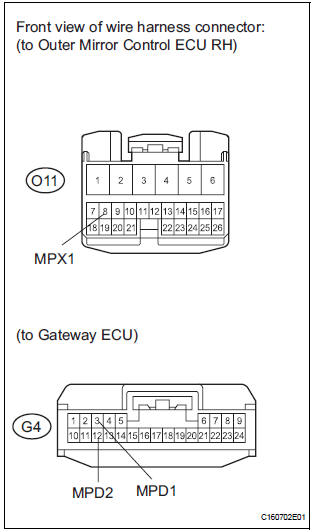
WIRING DIAGRAM
INSPECTION PROCEDURE
1 CHECK HARNESS AND CONNECTOR (OUTER MIRROR CONTROL ECU RH - BATTERY)
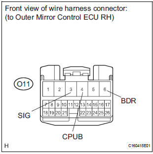
- Disconnect the O11 ECU connector.
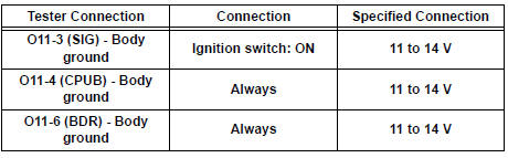
- Measure the voltage according to the value(s) in the table below.
Standard voltage
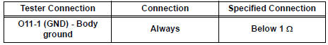
2 CHECK HARNESS AND CONNECTOR (OUTER MIRROR CONTROL ECU RH - GROUND)
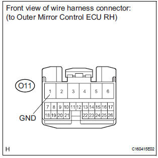
- Measure the resistance according to the value(s) in the table below.
Standard resistance
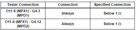
3 CHECK COMMUNICATION LINE
- Disconnect the G4 ECU connector.
- Measure the resistance according to the value(s) in the table below.
Standard resistance
Result
REPLACE OUTER MIRROR CONTROL ECU RH
 MPX Body ECU Stop
DTC B1200 MPX Body ECU Stop
DESCRIPTION
This DTC is detected when communication between the multiplex network body
ECU and the multiplex
network gateway ECU stops for more than 10 seconds.
...
 Driver Side Outer Mirror
DTC B1209 Driver Side Outer Mirror
DESCRIPTION
This DTC is detected when communication between the outer mirror control ECU
LH and multiplex
network gateway ECU stops for more than 10 seconds
...
Other materials:
Fuel Pump Control Circuit
DESCRIPTION
The FUEL PUMP relay switches the fuel pump speed according to the engine
conditions. The fuel pump
operates when the ECM receives the starter-operating signal (STA) and
crankshaft-rotating signal (NE).
The FUEL PUMP relay is turned ON while the engine is idling or operating at l ...
Installation
1. INSTALL STEERING ANGLE SENSOR
(a) Install the steering sensor onto the spiral cable.
2. PLACE FRONT WHEELS FACING STRAIGHT AHEAD
3. INSTALL SPIRAL CABLE SUB-ASSEMBLY (See page
RS-434)
4. INSTALL STEERING COLUMN COVER LWR (See
page RS-435)
5. CENTER SPIRAL CABLE (See page RS-435)
6. IN ...
Short to B+ in CAN Bus Line
DESCRIPTION
A short to B+ is suspected in the CAN bus wire when the resistance between
terminals 6 (CANH) and 16
(BAT), or terminals 14 (CANL) and 16 (BAT) of the DLC3 is below 6 kΩ.
Symptom
Trouble Area
The resistance between terminals 6 (CANH) and 16 (BAT), or
...
