Toyota Sienna Service Manual: Push Switch / Key Unlock Warning Switch Malfunction
DTC B2780 Push Switch / Key Unlock Warning Switch Malfunction
DESCRIPTION
This DTC will be output if the transponder key ECU does not detect that the unlock warning switch is on even when the ignition switch is on (Under the normal conditions, the unlock warning switch is on when the ignition switch is on).
|
DTC No. |
DTC Detection Condition |
Trouble Area |
|
B2780 |
Unlock warning switch on is not detected when ignition switch is on |
|
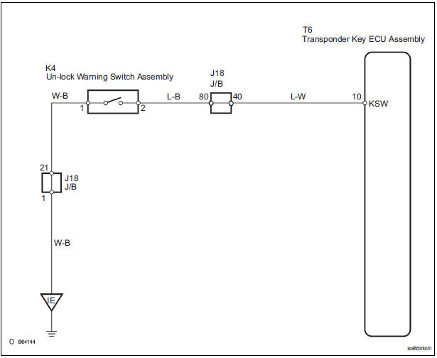
WIRING DIAGRAM
INSPECTION PROCEDURE
1 READ VALUE OF INTELLIGENT TESTER
- Connect the intelligent tester (with CAN VIM) to the DLC3.
- Turn the ignition switch on and turn the intelligent tester main switch on.
- Select KEY SW in the DATA LIST and read the value displayed on the intelligent tester.
Transponder key ECU:
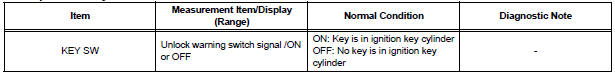
OK: ON (Key is in ignition key cylinder) appears on the screen
2 INSPECT UNLOCK WARNING SWITCH ASSEMBLY
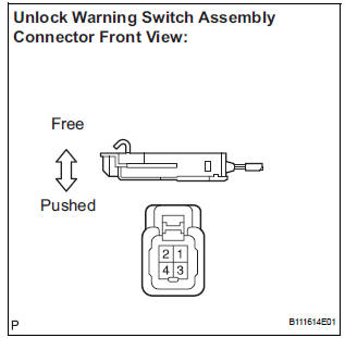
- Remove the unlock warning switch.
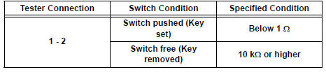
- Measure the resistance according to the value(s) in the table below.
Resistance
3 CHECK HARNESS AND CONNECTOR (TRANSPONDER KEY ECU ASSEMBLY - UNLOCK WARNING SW ASSEMBLY)
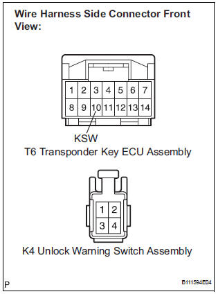
- Disconnect the T6 ECU and K4 switch connectors.
- Measure the resistance according to the value(s) in the table below.
Resistance
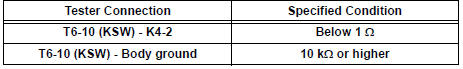
4 CHECK HARNESS AND CONNECTOR (UNLOCK WARNING SW ASSEMBLY - BODY GROUND)
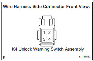
- Measure the resistance according to the value(s) in the table below.
Resistance

REPLACE TRANSPONDER KEY ECU ASSEMBLY
 Diagnostic trouble code chart
If a trouble code is displayed during the DTC check, check
the circuit listed for that code. For details of each code, turn
the page mentioned below the "DTC No" in the DTC chart.
the & ...
 Antenna Coil Open / Short
DTC B2784 Antenna Coil Open / Short
DESCRIPTION
The transponder key coil is built into the transponder key amplifier and
receives a key code signal from
the transponder chip in the key. This sign ...
Other materials:
Combination Meter ECU Communication Stop
DTC B1271 Combination Meter ECU Communication Stop
DESCRIPTION
DTC B1271 is output when communication between the combination meter and the
multiplex network
gateway ECU stops for more than 10 seconds.
DTC No.
DTC Detection Condition
Trouble Area
B1271
...
Stowing the third seats (manual seats)
Before stowing or returning third seat, remove any items from the floor
area to prevent interference with moving parts.
Before stowing the third seats
Lower the center head
restraint to the lowest position
, and stow the
seat belt buckles.
Stow the center seat belt.
Stowing ...
No. 1 Clearance Warning Buzzer Circuit
DESCRIPTION
The clearance warning ECU receives the ultrasonic sensor signal to sound the
front warning buzzer.
WIRING DIAGRAM
INSPECTION PROCEDURE
1 INSPECT FRONT BUZZER
Remove the clearance warning ECU with front buzzer.
Apply the battery voltage to the terminals 1 and 2 o ...
