Toyota Sienna Service Manual: Radio Broadcast cannot be Received or Poor Reception
INSPECTION PROCEDURE
1 CHECK RADIO AND NAVIGATION ASSEMBLY
- Check the radio's automatic station search function.
- Check the radio's automatic station search function by activating it.
OK: The radio's automatic station search function works properly.
2 INSPECT RADIO AND NAVIGATION ASSEMBLY
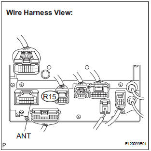
- Disconnect the radio and navigation assembly connector R15.
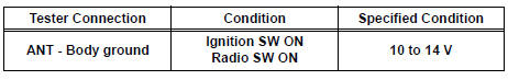
- Measure the voltage according to the value(s) in the table below.
Standard voltage
3 CHECK OPTIONAL COMPONENTS
- Check optional components (sun-shade film, telephone antenna, etc.).
- Check if any optional components, such as sunshade film or telephone antenna that may decrease reception capacity, are installed.
OK: Optional components are installed.
NOTICE: Do not remove any optional components installed by the customer without his or her consent
4 CHECK RADIO AND NAVIGATION ASSEMBLY
- Preparation for check
- Remove the antenna plug from the radio and navigation assembly.
- Check for noise
- Turn the ignition switch to the ACC position with the radio and navigation assembly connector connected.
- Turn the radio on and put into AM mode.
- Place a screwdriver, thin wire, or other metal object on the radio receiver's antenna jack and check that noise can be heard from the speaker.
OK: Noise occurs
5 CHECK GLASS ANTENNA
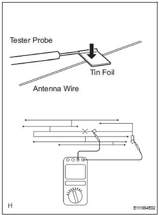
- Check for continuity of the antenna.
HINT: Check for continuity at the center of each antenna wire as shown in the illustration.
NOTICE: When cleaning the glass, wipe it in the direction of the wire with a soft dry cloth. Take care not to damage the wire. Do not use detergents or glass cleaners with abrasive ingredients. When measuring voltage, wrap a piece of tin foil around the tip of the negative probe and press the foil against the wire with your finger, as shown in the illustration.
OK: There is continuity in the antenna.
6 REPLACE ANTENNA AMPLIFIER
- Replace the antenna amplifier and check that it operates normally.
OK: The antenna amplifier operates normally
REPLACE RADIO AND NAVIGATION ASSEMBLY
 CD Sound Skips
INSPECTION PROCEDURE
1 CHECK CD
Check the CD.
OK:
The CD is clean.
HINT:
If dirt is on the CD surface, wipe it clean with a soft cloth
from the inside to the outside in a radial directio ...
 Illumination for Panel Switch does not Come on with Tail Switch ON
INSPECTION PROCEDURE
1 CHECK VEHICLE SIGNAL (DISPLAY CHECK MODE)
Enter the "Display Check" mode (Vehicle Signal Check Mode).
Check that the display changes between ON and OF ...
Other materials:
No. 2 Ultrasonic sensor
COMPONENTS
REMOVAL
1. REMOVE REAR BUMPER COVER (2)
2. REMOVE NO. 1 ULTRASONIC SENSOR RETAINER
Remove the No. 1 ultrasonic sensor retainer as
shown in the illustration
3. REMOVE NO. 2 ULTRASONIC SENSOR
Disconnect the connector and remove the No. 2
ultrasonic ...
Reassembly
1. INSTALL UNDERDRIVE CLUTCH DRUM O-RING
(a) Coat a new O-ring with ATF, and install it to the
underdrive clutch drum.
NOTICE:
Make sure that the O-ring is not twisted or
pinched.
2. INSTALL UNDERDRIVE CLUTCH PISTON SET
(a) Coat the underdrive clutch piston with ATF, and
install it t ...
Listening to a
USB memory device
Connecting a USB memory device enables you to enjoy music
from the vehicle speakers.
Touch “USB” on the audio source selection screen.
Connecting a USB memory device
Audio control screen
Pressing the “AUDIO” button displays the audio control screen from
any screens of the selected so ...
