Toyota Sienna Service Manual: Radio Receiver Communication Error
INSPECTION PROCEDURE
1 IDENTIFY THE COMPONENT SHOWN BY THE SUB-CODE
- Enter the diagnostic mode
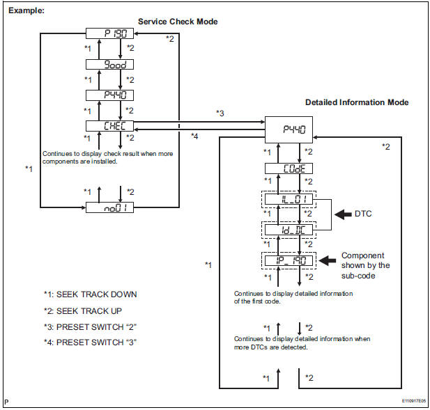
- Press the preset switch "3" to change to "Detailed Information Mode".
- Identify the component shown by the sub-code.
HINT:
- "190 (radio receiver)" is the component shown by the subcode in the example shown in the illustration.
- For details of the DTC display, refer to "DTC CHECK/ CLEAR"
2 CHECK POWER SOURCE CIRCUIT OF COMPONENT SHOWN BY SUB-CODE
- Inspect the power source circuit of the component shown
by the sub-code.
If the power source circuit is operating normally, proceed to the next step.
Component Table:
|
Component |
Proceed to |
| Stereo component amplifier (440) | Stereo component amplifier power source circuit |
| Television display assembly (1B0) | Television display assembly power source circuit |
3 INSPECT RADIO RECEIVER
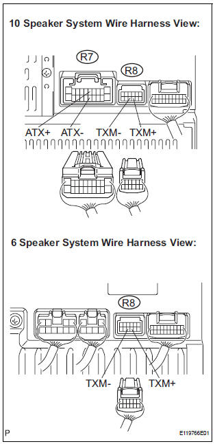
- Disconnect the radio receiver connectors.
- Measure the resistance according to the value(s) in the table below.
Standard resistance
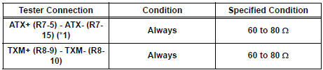
*1: 10 Speaker System
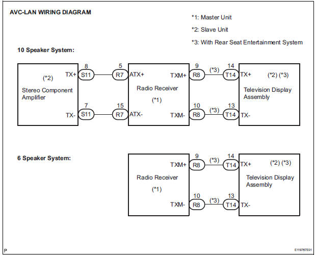
4 CHECK HARNESS AND CONNECTOR (RADIO RECEIVER - COMPONENT SHOWN BY SUB-CODE)
HINT:
- Start the check from the circuit that is near the component shown by the sub-code first.
- For details of the connectors, refer to the "TERMINALS OF ECU".
- Referring to the AVC-LAN wiring diagram below, check the AVC-LAN circuit between the radio receiver and the component shown by the sub-code.
- Disconnect all connectors between the radio receiver and the component shown by sub-code.
- Check for an open or short in the AVC-LAN circuit between the radio receiver and the component shown by the sub-code.
OK: There is no open or short circuit.
5 REPLACE COMPONENT SHOWN BY SUB-CODE
- Replace the component shown by the sub-code with a normal one and check if the same problem occurs again.
OK: Same problem does not occur.
END
 Vehicle Speed Signal Circuit between Stereo Component Amplifier and
Combination Meter
Vehicle Speed Signal Circuit between Stereo Component Amplifier and
Combination Meter
DESCRIPTION
This circuit is necessary for the ASL (Auto Sound Leveliser) built into the
stereo component amplifier.
Speed signals are received from the combination meter and used for the ASL.
...
 Stereo Component Amplifier Communication Error
INSPECTION PROCEDURE
1 IDENTIFY THE COMPONENT SHOWN BY THE SUB-CODE
Enter the diagnostic mode.
Press the preset switch "3" to change to "Detailed
Information Mode" ...
Other materials:
Driving in vehicle-to-vehicle distance control mode
This mode employs a radar sensor to detect the presence of vehicles
up to approximately 400 ft. (120 m) ahead, determines the current
vehicle-to-vehicle following distance, and operates to maintain a suitable
following distance from the vehicle ahead.
Note that vehicle-to-vehicle distance will ...
Inspection
1. INSPECT REAR DRIVE SHAFT ASSEMBLY LH
(a) Check that there is no remarkable play in the radial
direction of the outboard joint.
(b) Check that the inboard joint slides smoothly in the
thrust direction.
(c) Check that there is no remarkable play in the radial
direction of the inboard ...
Data list / active test
1. READ DATA LIST
HINT:
Using the intelligent tester to read the Data List allows
the values or states of switches, sensors, actuators and
other items to be read without removing any parts. This
non-intrusive inspection can be very useful because
intermittent conditions or signals may be disco ...
