Toyota Sienna Service Manual: Rear Air Outlet Damper Control Servo Motor Circuit
DESCRIPTION
This circuit turns the servo motor and changes each damper position by receiving the signals from the A/ C amplifier.
The rear air outlet damper servo motor switches the air outlet mode by rotating
(normal, reverse) with
electrical power from the A/C amplifier.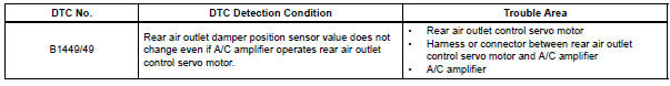
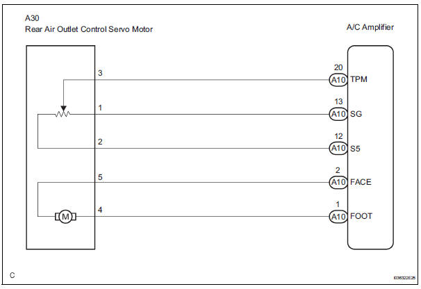
WIRING DIAGRAM
INSPECTION PROCEDURE
1 READ VALUE OF INTELLIGENT TESTER
(a) Connect the intelligent tester to the DLC3.
(b) Turn the ignition switch to the ON position and turn the intelligent tester main switch on.
(c) Select the items below in the DATA LIST, and read the display on the intelligent tester.
DATA LIST / AIR CONDITIONER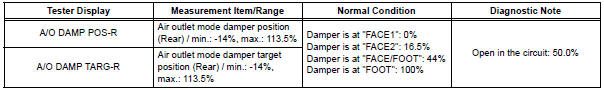
OK: When the target position is "FACE1" (0%), the actual opening angle is 19.0% or less.
When the target position is "FOOT" (100%), the actual opening angle is 81.0% or more.
Result 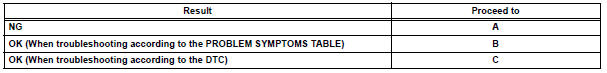

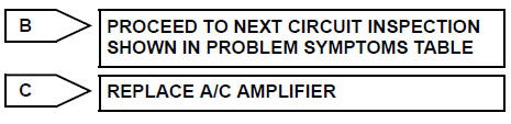
2 PERFORM ACTIVE TEST BY INTELLIGENT TESTER
(a) Connect the intelligent tester to the DLC3.
(b) Turn the ignition switch to the ON position and turn the intelligent tester main switch on.
(c) Select the item below in the ACTIVE TEST and then check the air flow position by hand.
ACTIVE TEST / AIR CONDITIONER
OK: Air comes out from the selected air outlet.
Result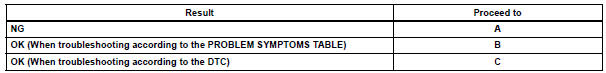

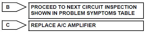
3 PERFORM ACTUATOR CHECK
(a) Warm up the engine.
(b) Enter the actuator check mode (See page AC-15).
(c) Press the DEF switch and change to step operation.
(d) Press the DEF switch and check the air flow by hand.
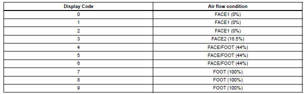
OK: Air outlet mode changes in accordance with each display code.
Result 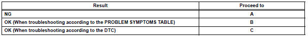

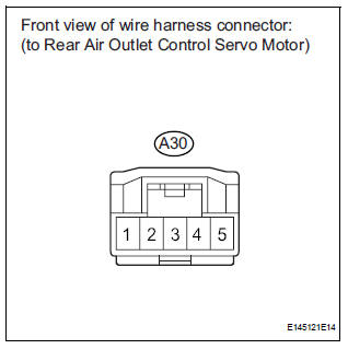
4 INSPECT REAR AIR OUTLET CONTROL SERVO MOTOR
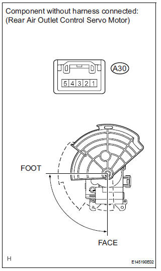
(a) Remove the rear air outlet control servo motor.
(b) Disconnect the connector from the rear air outlet control servo motor.
(c) Connect the positive (+) lead from the battery to terminal 4 and the negative (-) lead to terminal 5, then check that the lever turns to the "FOOT" position smoothly.
OK: Lever turns to "FOOT" position smoothly.

5 CHECK HARNESS AND CONNECTOR (REAR AIR OUTLET CONTROL SERVO MOTOR - A/C AMPLIFIER)
(a) Disconnect the connector from the A/C amplifier.
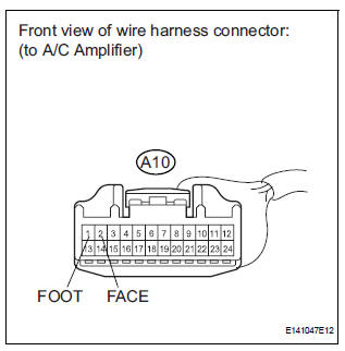
(b) Measure the resistance according to the value(s) in the table below.
Standard resistance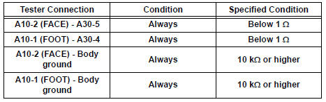

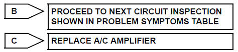
REPLACE A/C AMPLIFIER
 Rear Air Mix Damper Control Servo Motor Circuit
DESCRIPTION
The rear air mix control servo motor (water valve servo motor) is controlled
by the A/C amplifier.
The rear air mix control servo motor moves the air mix damper by rotating
(normal ...
 Compressor Solenoid Circuit
DESCRIPTION
In this circuit, the compressor receives a refrigerant compression demand
signal from the A/C amplifier.
Based on this signal, the compressor changes the amount of compressor output. ...
Other materials:
High pitched horn
COMPONENTS
REMOVAL
1. REMOVE FRONT BUMPER COVER
2. REMOVE HIGH PITCHED HORN
Disconnect the connector.
Remove the bolt and horn.
INSPECTION
1. INSPECT HIGH PITCHED HORN
Apply battery voltage and check operation of the
horn, as shown in the table.
Standard ...
Compressor Lock Sensor Circuit
DTC B1422/22 Compressor Lock Sensor Circuit
SYSTEM DESCRIPTION
The ECM sends an engine speed signal to the A/C amplifier via CAN
communication and BEAN
communication.
The A/C amplifier reads the difference between compressor speed and engine
speed. When the
difference becomes too large, t ...
System description
1. OUTLINE OF THEFT DETERRENT SYSTEM
When the theft deterrent system detects that the
vehicle is being tampered with, the system sets off
the alarm, causing the horns to sound and the lights
to light up or blink in order to alert people around the
vehicle to the theft.
The ...
