Toyota Sienna Service Manual: Rear combination light assembly
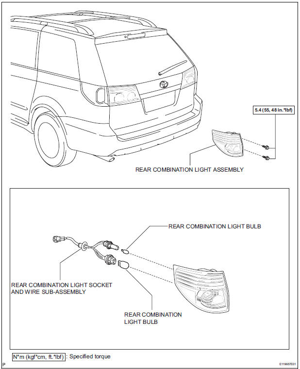
COMPONENTS
REMOVAL
1. DISCONNECT CABLE FROM NEGATIVE BATTERY TERMINAL
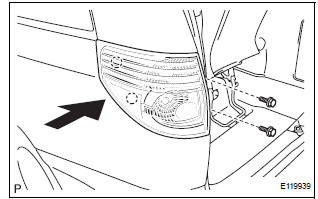
2. REMOVE REAR COMBINATION LIGHT ASSEMBLY
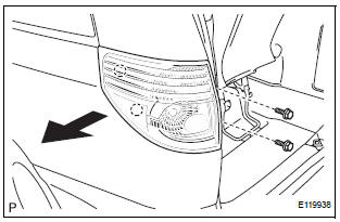
- Remove the 2 bolts.
- Disengage the 2 pins and separate the rear combination light assembly as shown in the illustration.
- Disconnect the connector and remove the rear combination light assembly.
DISASSEMBLY
1. REMOVE REAR COMBINATION LIGHT BULB
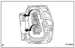
- Turn in the direction indicated by the arrow and separate the 2 rear combination light bulbs.
- Remove the 2 rear combination light bulbs from the rear combination light socket and wire subassembly.
REASSEMBLY
1. INSTALL REAR COMBINATION LIGHT BULB
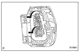
- Install the 2 rear combination light bulbs to the rear combination light socket and wire sub-assembly.
- Turn in the direction indicated by the arrow and install the 2 rear combination light bulbs to the rear combination light assembly.
INSTALLATION
1. INSTALL REAR COMBINATION LIGHT ASSEMBLY
- Connect the connector.
- Install the rear combination light assembly with the 2
bolts and 2 pins as shown in the illustration.
Torque: 5.4 N*m (55 kgf*cm, 48 in.*lbf)
2. CONNECT CABLE TO NEGATIVE BATTERY TERMINAL
 Installation
1. INSTALL FOG LIGHT ASSEMBLY
Install the fog light assembly with the 2 claws and 2
pins.
2. INSTALL FRONT BUMPER ASSEMBLY
3. CONNECT CABLE TO NEGATIVE BATTERY
TERMINAL
4. VEHICL ...
 Back-up light assembly
COMPONENTS
REMOVAL
1. REMOVE BACK DOOR GARNISH CENTER
2. REMOVE BACK DOOR SIDE GARNISH LH
3. REMOVE BACK DOOR SIDE GARNISH RH
4. REMOVE BACK DOOR STRAP COVER SUBASSEMBLY
5. REMOVE BACK D ...
Other materials:
All Doors cannot be Locked / Unlocked at Once
DESCRIPTION
The body ECU receives a switch signal from the master switch, the door
control switch, the driver door
key cylinder and the passenger door key cylinder and then drives the door lock
motor.
WIRING DIAGRAM
INSPECTION PROCEDURE
1 INSPECT FUSE (ECU-B)
Remove ECU-B fuse f ...
Short to GND in Driver Side Squib Circuit
DTC B0102/11 Short to GND in Driver Side Squib Circuit
DESCRIPTION
The driver side squib circuit consists of the center airbag sensor assembly,
the spiral cable and the
steering pad.
The circuit instructs the SRS to deploy when deployment conditions are met.
DTC B0102/11 is recorded when ...
How to proceed with
troubleshooting
HINT:
*: Use the intelligent tester.
1 VEHICLE BROUGHT TO WORKSHOP
2 CUSTOMER PROBLEM ANALYSIS
(a) Confirm problem symptoms
3 CHECK MULTIPLEX COMMUNICATION SYSTEM*
Check if the multiplex communication system DTC is output.
HINT:
The center airbag sensor assembly of this system ...
