Toyota Sienna Service Manual: Rear evaporator temperature sensor circuit
DESCRIPTION
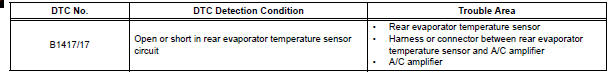
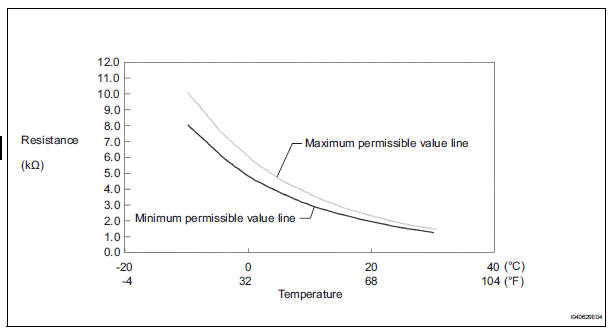
The rear evaporator temperature sensor is installed on the rear evaporator. It detects the rear evaporator temperature. The sensor sends a signal to the A/C amplifier. The resistance of the rear evaporator temperature sensor changes in accordance with the rear evaporator temperature. As the temperature decreases, the resistance increases. As the temperature increases, the resistance decreases.
The A/C amplifier applies voltage (5 V) to the rear evaporator temperature
sensor and reads voltage
changes as the resistance of the rear evaporator temperature sensor changes.
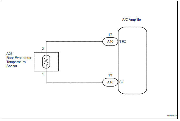
WIRING DIAGRAM
INSPECTION PROCEDURE
1 READ VALUE OF INTELLIGENT TESTER
(a) Connect the intelligent tester to the DLC3.
(b) Turn the ignition switch to the ON position and turn the intelligent tester main switch on.
(c) Select the item below in the DATA LIST, and read the display on the intelligent tester.
DATA LIST / AIR CONDITIONER: 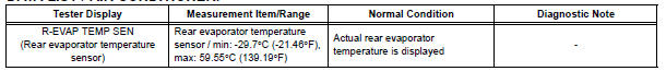
OK: The display is as specified in the normal condition column.
Result 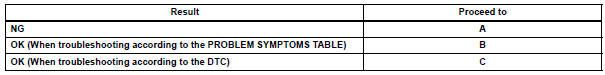

2 INSPECT REAR EVAPORATOR TEMPERATURE SENSOR
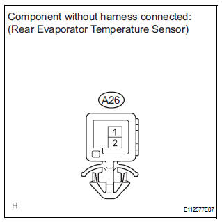
(a) Remove the rear evaporator temperature sensor.
(b) Measure the resistance according to the value(s) in the table below.
Standard resistance 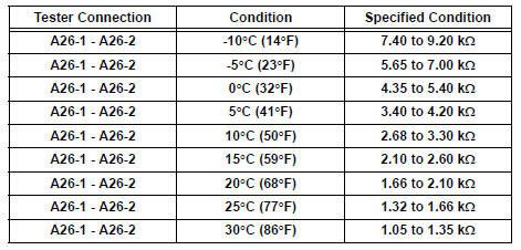
NOTICE:
- Even slightly touching the sensor may change the resistance value. Be sure to hold the connector of the sensor.
- When measuring, the sensor temperature must be the same as the rear evaporator temperature.
HINT: As the temperature increases, the resistance decreases (see the graph).

3 CHECK HARNESS AND CONNECTOR (REAR EVAPORATOR TEMPERATURE SENSOR - A/C AMPLIFIER)
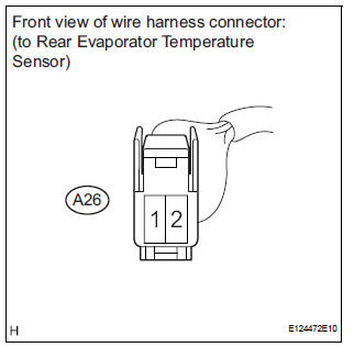
(a) Disconnect the rear evaporator temperature sensor connector.
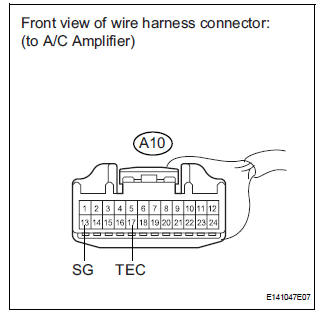
(b) Disconnect the A/C amplifier connector.
(c) Measure the resistance according to the value(s) in the table below.
Standard resistance 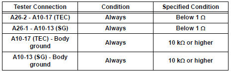

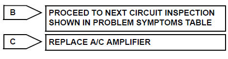
REPLACE A/C AMPLIFIER
 Evaporator temperature sensor circuit
DESCRIPTION
The evaporator temperature sensor (A/C thermistor) is installed on the
evaporator in the air conditioning
unit. It detects the temperature of the cooled air that has passed through the ...
 Rear Room Temperature Sensor Circuit
DESCRIPTION
This sensor detects the rear cabin temperature that is used as the basis for
temperature control and
sends a signal to the A/C amplifier.
WIRING DIAGRAM
INSPECTION PROCEDURE
1 R ...
Other materials:
Short in Front Pretensioner Squib RH Circuit
DTC B0130/63 Short in Front Pretensioner Squib RH Circuit
DESCRIPTION
The front pretensioner squib RH circuit consists of the center airbag sensor
assembly and the front seat
outer belt assembly RH.
This circuit instructs the SRS to deploy when deployment conditions are met.
DTC B0130/63 ...
Front Occupant Classification Sensor LH Collision
Detection
DTC B1785 Front Occupant Classification Sensor LH Collision
Detection
DESCRIPTION
DTC B1785 is output when the occupant classification ECU receives a collision
detection signal sent by
the front occupant classification sensor LH if an accident occurs.
DTC B1785 is also output when the front ...
GPS Mark is not Displayed
INSPECTION PROCEDURE
1 CHECK CABIN
Check the cabin for any object that might interrupt radio
reception on the instrument panel. If such an object
exists, remove it and check if the GPS mark reappears.
HINT:
The GPS uses extremely faint radio waves originating
from satellites. If the si ...
