Toyota Sienna Service Manual: Rear Occupant Classification Sensor RH Collision Detection
DTC B1788 Rear Occupant Classification Sensor RH Collision Detection
DESCRIPTION
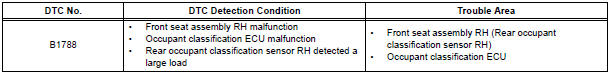
DTC B1788 is output when the occupant classification ECU receives a collision detection signal sent by the rear occupant classification sensor RH if an accident occurs.
DTC B1788 is also output when the front seat assembly RH is subjected to a strong impact, even if an actual accident does not occur.
However, when the occupant classification ECU outputs a collision detection signal, even if the vehicle is not in a collision, DTC B1788 can be cleared by "Zero point calibration" and "Sensitivity check".
Therefore, if DTC B1788 is output, first perform "Zero point calibration" and "Sensitivity check".
WIRING DIAGRAM
INSPECTION PROCEDURE
1 PERFORM ZERO POINT CALIBRATION
- Connect the intelligent tester to the DLC3.
- Turn the ignition switch to the ON position.
- Using the intelligent tester, perform "Zero point calibration".
OK: "COMPLETED" is displayed.
2 PERFORM SENSITIVITY CHECK
- Using the intelligent tester, perform "Sensitivity check".
Standard value: 27 to 33 kg (59.52 to 72.75 lb)
3 CHECK DTC
- Turn the ignition switch to the ON position.
- Clear the DTCs stored in the memory HINT: First clear DTCs stored in the occupant classification ECU and then in the center airbag sensor assembly.
- Turn the ignition switch to the LOCK position.
- Turn the ignition switch to the ON position.
- Check the DTCs.
OK: DTC B1788 is not output.
HINT: Codes other than DTC B1788 may be output at this time, but they are not related to this check.
4 REPLACE FRONT SEAT ASSEMBLY RH
- Turn the ignition switch to the LOCK position.
- Disconnect the negative (-) terminal cable from the battery, and wait for at least 90 seconds.
- Replace the front seat assembly RH ( for flat type, SE-48 for manual seat, SE-58 for power seat).
HINT: Perform the inspection using parts from a normal vehicle if possible
5 PERFORM ZERO POINT CALIBRATION
- Connect the negative (-) terminal cable to the battery.
- Connect the intelligent tester to the DLC3.
- Turn the ignition switch to the ON position.
- Using the intelligent tester, perform "Zero point calibration".
OK: "COMPLETED" is displayed.
6 PERFORM SENSITIVITY CHECK
- Using the intelligent tester, perform "Sensitivity check".
Standard value: 27 to 33 kg (59.52 to 72.75 lb)
7 CHECK DTC
- Turn the ignition switch to the ON position.
- Clear the DTCs stored in the memory.
HINT: First clear DTCs stored in the occupant classification ECU and then in the center airbag sensor assembly.
- Turn the ignition switch to the LOCK position.
- Turn the ignition switch to the ON position.
- Check the DTCs.
OK: DTC B1788 is not output.
HINT: Codes other than DTC B1788 may be output at this time, but they are not related to this check.
8 REPLACE OCCUPANT CLASSIFICATION ECU
- Turn the ignition switch to the LOCK position.
- Disconnect the negative (-) terminal cable from the battery, and wait for at least 90 seconds.
- Replace the occupant classification ECU
9 PERFORM ZERO POINT CALIBRATION
- Connect the negative (-) terminal cable to the battery.
- Connect the intelligent tester to the DLC3.
- Turn the ignition switch to the ON position.
- Using the intelligent tester, perform "Zero point calibration".
OK: "COMPLETED" is displayed.
10 PERFORM SENSITIVITY CHECK
- Using the intelligent tester, perform "Zero point calibration".
Standard value: 27 to 33 kg (59.52 to 72.75 lb)
END
 Rear Occupant Classification Sensor LH Collision
Detection
Rear Occupant Classification Sensor LH Collision
Detection
DTC B1787 Rear Occupant Classification Sensor LH Collision
Detection
DESCRIPTION
DTC B1787 is output when the occupant classification ECU receives a collision
detection signal sent by
the rear o ...
 Center Airbag Sensor Assembly Communication
Circuit Malfunction
Center Airbag Sensor Assembly Communication
Circuit Malfunction
DTC B1790 Center Airbag Sensor Assembly Communication
Circuit Malfunction
DESCRIPTION
The center airbag sensor assembly communication circuit consists of the
occupant classification ECU and
the ...
Other materials:
Washer fluid
If any washer does not work or the
warning message appears on the
multi-information display, the
washer tank may be empty. Add
washer fluid.
WARNINGWhen refilling washer fluid
Do not refill washer fluid when the engine is hot or running, as
washer fluid
contains alcohol and ...
ECM
COMPONENTS
REMOVAL
1. REMOVE GLOVE COMPARTMENT DOOR ASSEMBLY
(a) Push the right side wall and then push the left wall
to release the stoppers.
(b) Pull the glove compartment door sub-assembly
rearward to remove it.
2. REMOVE NO. 2 INSTRUMENT PANEL BOX
(a) Disengage the 2 claws ...
Disassembly
1. REMOVE OCCUPANT CLASSIFICATION ECU
2. REMOVE FRONT SEAT CUSHION SHIELD INNER RH
Remove the screw.
Using a screwdriver, disengage the claws and
remove the cushion shield inner.
HINT:
Tape the screwdriver tip before use.
3. REMOVE FRONT SEAT INNER BELT ASSEMBLY RH
&nbs ...
