Toyota Sienna Service Manual: Rear view monitor system
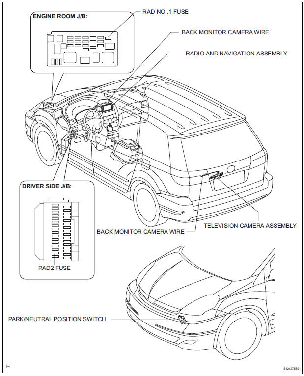
PARTS LOCATION
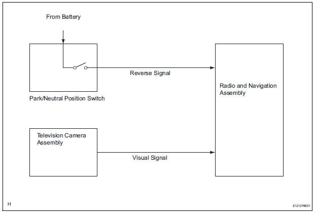
SYSTEM DIAGRAM

 System description
1. GENERAL
To assist the driver with parking the vehicle by
displaying an image of the area behind the vehicle,
this system has a television camera mounted on the
luggage compartment d ...
Other materials:
SFR Solenoid Circuit
DESCRIPTION
The solenoid comes on when signals are received from the ECU and controls the
pressure acting on the
wheel cylinders, thus controlling brake force.
WIRING DIAGRAM
INSPECTION PROCEDURE
1 RECONFIRM DTC
HINT:
These codes are detected when a problem is identified in the
...
Camshaft Position "A" - Timing Over
HINT:
If DTC P0011, P0012, P0021 or P0022 is present, check the VVT (Variable Valve
Timing) system.
DESCRIPTION
Refer to DTC P0010 (See page ES-75).
DTC No.
DTC Detection Condition
Trouble Area
P0011
P0021
Advanced cam timing:
With warm engine and engine spee ...
Random / Multiple Cylinder Misfire Detected
DESCRIPTION
When the engine misfires, high concentrations of hydrocarbons (HC) enter the
exhaust gas. High HC
concentration levels can cause increase in exhaust emission levels. Extremely
high concentrations of HC
can also cause increases in the Three-Way Catalytic Converter (TWC) tem ...
