Toyota Sienna 2010-2024 Owners Manual: Rear view monitor system precautions
Area displayed on screen
The rear view monitor system displays an image of the view from the bumper of the rear area of the vehicle.
The image on the rear view monitor system can be adjusted.
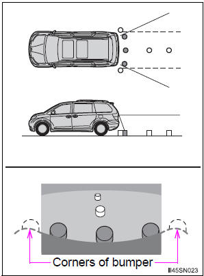
- The area displayed on the screen may vary according to vehicle orientation conditions.
- Objects which are close to either corner of the bumper or under the bumper cannot be displayed.
- The camera uses a special lens.
The distance of the image that appears on the screen differs from the actual distance.
- Items which are located higher than the camera may not be displayed on the monitor.
- If your vehicle is equipped with a backlit license plate, it may interfere with the display.
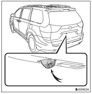
Rear view monitor system camera
The camera for the rear view monitor system is located above the license plate.
- Using the camera
If dirt or foreign matter (such as water droplets, snow, mud etc.) is adhering to the camera, it cannot transmit a clear image. In this case, flush it with a large quantity of water and wipe the camera lens clean with a soft and wet cloth.
Differences between the screen and the actual road
The distance guide lines and the vehicle width guide lines may not actually be parallel with the dividing lines of the parking space, even when they appear to be so. Be sure to check visually.
The distances between the vehicle width guide lines and the left and right dividing lines of the parking space may not be equal, even when they appear to be so. Be sure to check visually.
The distance guide lines give a distance guide for flat road surfaces.
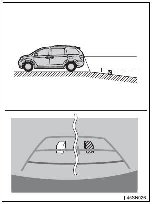
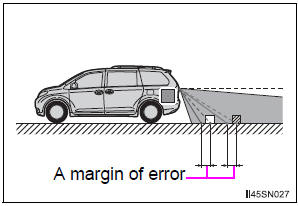
In any of the following situations, there is a margin of error between the fixation guide lines on the screen and the actual distance/ course on the road.
- When the ground behind the vehicle slopes up sharply
The distance guide lines will
appear to be closer to the
vehicle than the actual distance.
Because of this, objects will appear to be farther away than they actually are. In the same way, there will be a margin of error between the guide lines and the actual distance/course on the road.
- When the ground behind the vehicle slopes down sharply
The distance guide lines will
appear to be further from the
vehicle than the actual distance.
Because of this, objects will appear to be closer than they actually are.
In the same way, there will be a margin of error between the guide lines and the actual distance/course on the road
- When any part of the vehicle sags When any part of the vehicle sags due to the number of passengers or the distribution of the load, there is a margin of error between the fixation guide lines on the screen and the actual distance/ course on the road.
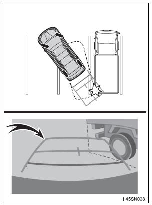
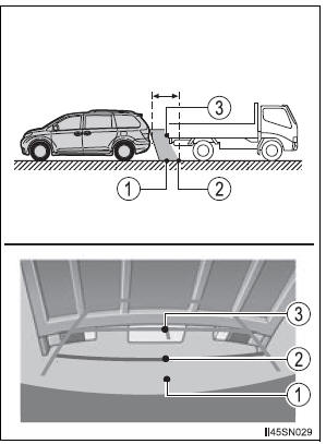
When approaching three-dimensional objects
The distance guide lines are displayed according to flat surfaced objects (such as the road). It is not possible to determine the position of three-dimensional objects (such as vehicles) using the distance guide lines. When approaching a three-dimensional object that extends outward (such as the flatbed of a truck), be careful of the following.
- Vehicle width guide lines Visually check the surroundings and the area behind the vehicle. In the case shown in the illustration, the truck appears to be outside of the vehicle width guide lines and the vehicle does not look as if it hits the truck. However, the rear body of the truck may actually cross over the vehicle width guide lines. In reality if you back up as guided by the vehicle width guide lines, the vehicle may hit the truck.
- Distance guide lines Visually check the surroundings and the area behind the vehicle. On the screen, it appears that a truck is parking at point 2. However, in reality if you back up to point 1, you will hit the truck. On the screen, it appears that 1 is closest and 3 is farthest away. However, in reality, the distance to 1 and 3 is the same, and 2 is farther than 1 and 3.
 Using the rear view monitor system
Screen description
The rear view monitor system screen will be displayed if the shift
lever is shifted to R while the engine switch is in the “ON” position
(vehicles without a smart key system) ...
 Things you should know
If you notice any symptoms
If you notice any of the following symptoms, refer to the likely cause
and the solution, and re-check.
If the symptom is not resolved by the solution, have the vehicle
...
Other materials:
Registering and connecting from the “Bluetooth* Setup” screen
To display the screen shown below, press the “SETUP” button and
select “Bluetooth*” on the “Setup” screen.
Select to connect the device to
be used with audio system.
Select to register a Bluetooth® device to be used with audio system.
Select to set detailed
Blueto ...
Oxygen (A/F) Sensor Heater Control Circuit
Low/ Oxygen (A/F) Sensor Heater Control Circuit
High
DTC P0031 Oxygen (A/F) Sensor Heater Control Circuit
Low (Bank 1 Sensor 1)
DTC P0032 Oxygen (A/F) Sensor Heater Control Circuit
High (Bank 1 Sensor 1)
DTC P0051 Oxygen (A/F) Sensor Heater Control Circuit
Low (Bank 2 Sensor 1)
DTC P0052 Oxygen (A/F) Sensor Heater Control Circuit
High (Bank 2 S ...
DSP Error
DTC 44-78 DSP Error
DESCRIPTION
DTC No.
DTC Detection Condition
Trouble Area
44-78
An error occurs during the decode process (MP3 /
WMA).
-
INSPECTION PROCEDURE
HINT:
After the inspection is completed, clear the DTCs.
NOTICE:
Th ...
