Toyota Sienna Service Manual: Reassembly
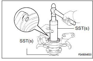
1. INSTALL FRONT AXLE HUB LH BEARING
(a) Using SST(s) and a press, install a new front axle hub LH bearing to the steering knuckle LH.
SST 09950-60020 (09951-00810), 09950-70010 (09951-07100)
2. INSTALL DISC BRAKE DUST COVER FRONT LH
(a) Place the disc brake dust cover front LH and using a torx wrench (T30), torque the 4 bolts.
Torque: 8.3 N*m (85 kgf*cm, 74 in.*lbf)
HINT: Torx is a registered trademark of Textron Inc.
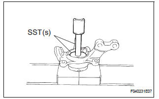
3. INSTALL FRONT AXLE HUB SUB-ASSEMBLY LH
(a) Using SST(s), and a press, install the front axle hub sub-assembly LH.
SST 09608-32010, 09950-60020 (09951-00810), 09950-70010 (09951-07100)
4. INSTALL FRONT AXLE HUB LH HOLE SNAP RING
(a) Using snap ring pliers, install a new front axle hub LH hole snap ring.
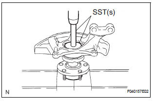
5. INSTALL FRONT WHEEL BEARING DUST DEFLECTOR NO.1 LH
(a) Using SST(s) and a hammer, install the bearing dust deflector No. 1 LH.
SST 09316-60011 (09316-00011, 09316-00031), 09608-32010
HINT: Align the hole for the speed sensor in the bearing dust deflector No. 1 LH with the steering knuckle.
6. INSTALL LOWER BALL JOINT ASSEMBLY FRONT LH
(a) Install the lower ball joint assembly front LH and tighten the nut.
Torque: 123 N*m (1,250 kgf*cm, 91 ft.*lbf) (b) Install a new cotter pin.
NOTICE: If the holes for the cotter pin are not aligned, tighten the nut up to 60° further.
 Disassembly
1. REMOVE LOWER BALL JOINT ASSEMBLY FRONT LH
(a) Remove the cotter pin and nut.
(b) Using SST(s), remove the lower ball joint assembly
front LH.
SST 09628-62011
2. REMOVE FRONT WHEEL BEAR ...
 Installation
1. INSTALL FRONT AXLE ASSEMBLY LH
(a) Install the 2 bolts, nuts and front axle assembly LH
with the 2 bolts and nuts to the shock absorber
assembly front LH.
Torque: 230 N*m (2,350 kgf*cm, 170 ...
Other materials:
Fuel Pump Primary Circuit
DESCRIPTION
This DTC is designed to detect a malfunction in the fuel pump (FUEL
PUMP) relay circuit. When the
system is normal, the battery voltage is applied to FPR terminal of the ECM
while the FUEL PUMP
relay is turned OFF. If the battery voltage is not applied to the FPR
ter ...
Command list
Some recognizable voice commands and their actions are shown
below as examples.
Basic
Command
Action
“Help”
Prompts voice guidance to offer examples of commands
or operation methods
“Go Back”
Returns to the previous screen
Phone
...
Inspection
1. INSPECT FRONT DIFFERENTIAL
(a) Using a dial indicator, measure the backlash of one
pinion gear while holding the front differential side
gear toward the case.
Standard backlash:
0.05 - 0.20 mm (0.0020 - 0.0079 in.)
NOTICE:
Do not mount the surface of front differential
case which cont ...
