Toyota Sienna Service Manual: Reassembly
1. INSTALL RACK STEERING PISTON RING
(a) Coat a new O-ring with power steering fluid and install it onto the power steering rack.
(b) Expand a new rack steering piston ring with your fingers.
NOTICE: Be careful not to over expand the rack steering piston ring.
(c) Coat a new rack steering piston ring with power steering fluid.
(d) Install the rack steering piston ring onto the power steering rack, and settle it down with your fingers.
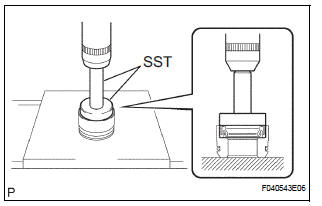
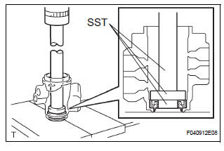
2. INSTALL POWER STEERING CYLINDER TUBE OIL SEAL
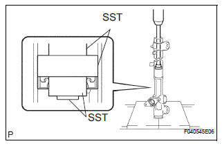
(a) Coat a new cylinder tube oil seal lip with power steering fluid.
(b) Using SST and a press, install the cylinder tube oil seal.
SST 09950-60010 (09951-00420, 09951-00250, 09952-06010), 09950-70010 (09951-07360)
NOTICE:
- Make sure that the cylinder tube oil seal is installed facing in the correct direction.
- Take care so that the cylinder tube oil seal will not be reversed as you install it.
3. INSTALL POWER STEERING RACK
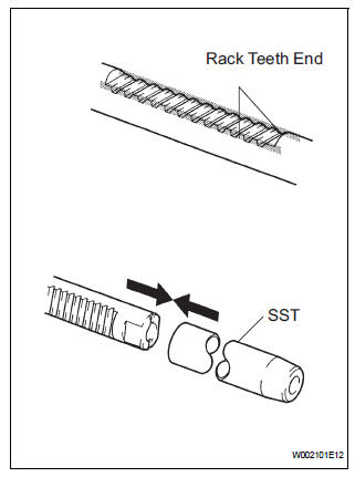
(a) Install SST onto the power steering rack.
SST 09631-33010
HINT: If necessary, scrape the burrs off the power steering rack teeth end and burnish.
(b) Coat the SST with power steering fluid.
(c) Install the power steering rack into the rack housing.
(d) Remove the SST.
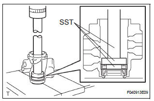
4. INSTALL POWER STEERING RACK BUSH
(a) Using SST and a press, install the rack bush oil seal onto the rack bush.
SST 09950-60010 (09951-00400), 09950-70010 (09951-07100)
NOTICE: Make sure that the rack bush oil seal is installed facing in the correct direction.
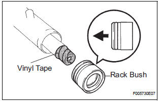
(b) Coat a new O-ring with power steering fluid and install it onto the rack bush.
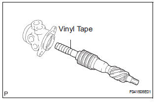
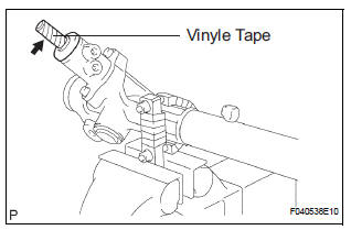
(c) To prevent rack bush oil seal lip damage, wind vinyl tape around the rack end, and apply power steering fluid.
(d) Install the rack bush onto the power steering rack.
5. INSTALL CYLINDER END STOPPER
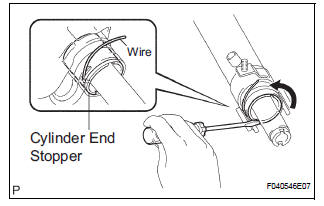
(a) Align the installation hole for the wire of the cylinder end stopper with the slot of the rack housing.
(b) Install a new wire into the cylinder end stopper.
(c) Using a screwdriver, turn the cylinder end stopper counterclockwise by 450 +- 50°.
6. AIR TIGHTNESS TEST
(a) Install SST onto the rack housing.
SST 09631-12071 (09633-00010) (b) Apply vacuum of 53 kPa (400 mmHg, 15.75 in.Hg) for about 30 seconds.
(c) Check that there is no change in the vacuum.
If there is a change in the vacuum, check the installation of the oil seals.
7. INSTALL POWER STEERING CONTROL VALVE UPPER OIL SEAL
(a) Coat a control valve upper bearing and a new control valve upper oil seal with power steering fluid.
(b) Using SST and a press, install the control valve upper oil seal.
SST 09950-70010 (09951-07150), 09950-60010 (09951-00180, 09952-06010, 09951-00320)
(c) Using SST and a press, install the control valve upper bearing.
SST 09950-70010 (09951-07150), 09950-60010 (09951-00180, 09952-06010, 09951-00340)
8. INSTALL POWER STEERING CONTROL VALVE
(a) Expand 4 new control valve rings with your fingers.
NOTICE: Be careful not to over expand the control valve rings.
(b) Coat the 4 control valve rings with power steering fluid.
(c) Install the 4 control valve rings onto the control valve, and settle them down with your fingers.
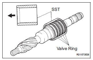
(d) Carefully slide the tapered end of SST over the control valve rings until they fit to the control valve.
SST 09631-20081
NOTICE: Be careful not to damage the control valve rings.
(e) To prevent control valve upper oil seal lip damage, wind vinyl tape around the serrated part of the control valve.
(f) Coat the control valve upper oil seal lip with power steering fluid.
(g) Install the control valve onto the control valve housing.
NOTICE: Be careful not to damage the control valve ring and control valve upper oil seal lip.
(h) Coat a new oil seal lip with power steering fluid.
(i) Using SST and a press, install the oil seal.
SST 09612-22011
NOTICE: Make sure that the oil seal is installed facing in the correct direction.
(j) Apply grease to the needle roller bearing.
(k) Install a new gasket onto the control valve housing.
(l) Wind vinyl tape around the serrated part of the control valve.
(m) Install the control valve w/ control valve housing onto the rack housing with the 2 bolts.
Torque: 18 N*m (184 kgf*cm, 13 ft.*lbf)
(n) Using SST, hold the control valve rotation and install a new lock nut.
SST 09616-00011 Torque: 25 N*m (250 kgf*cm, 18 ft.*lbf)
(o) Apply sealant to 2 or 3 threads of the rack housing cap.
Sealant: Toyota Genuine Adhesive 1344, Three Bond 1344, or equivalent
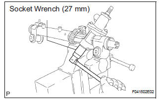
(p) Using a socket wrench (27 mm), install the rack housing cap.
Torque: 59 N*m (597 kgf*cm, 43 ft.*lbf)
(q) Using a punch and a hammer, stake the rack housing cap and rack housing.
9. INSTALL RACK GUIDE
(a) Install the rack guide.
(b) Install the compression spring.
(c) Apply sealant to 2 or 3 threads of the rack guide spring cap.
Sealant: Toyota Genuine Adhesive 1344, Three Bond 1344, or equivalent
(d) Temporarily install the rack guide spring cap.
10. INSTALL TOTAL PRELOAD
(a) To prevent the steering rack teeth from damaging the oil seal lip, temporarily install the RH and LH steering rack ends sub-assembly.
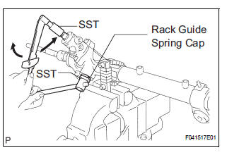
(b) Using SST, torque the rack guide spring cap.
SST 09631-10021 Torque: 25 N*m (254 kgf*cm, 18 ft.*lbf)
(c) Using SST, loosen the rack guide spring cap.
SST 09631-10021
d) Using SST, turn the control valve to the right and left 1 or 2 times.
SST 09616-00011 (e) Using SST, loosen the rack guide spring cap until the compression spring is not functioning.
SST 09631-10021
(f) Using SST and a torque wrench, tighten the rack guide spring cap until the preload is within specification.
SST 09631-10021, 09616-00011 Torque: Preload (turning) 1.2 to 1.5 N*m (12.2 to 15.3 kgf*cm, 10.6 to 13.3 in.*lbf)
(g) Apply sealant to 2 or 3 threads of the rack guide spring cap nut.
Sealant: Toyota Genuine Adhesive 1344, Three Bond 1344, or equivalent
(h) Temporarily install the rack guide spring cap nut.
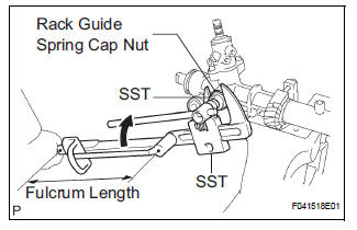
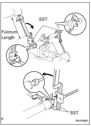
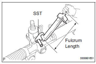
(i) Using SST, hold the rack guide spring cap and using another SST, torque the rack guide spring cap nut.
SST 09616-00011, 09922-10010 Torque: 48 N*m (489 kgf*cm, 35 ft.*lbf)
NOTICE: Use SST 09922-10010 in the direction shown in the illustration.
HINT: Use a torque wrench with a fulcrum length of 345 mm (13.58 in.).
(j) Precheck the total preload.
Torque: Preload (turning) 1.2 to 1.5 N*m (12.2 to 15.3 kgf*cm, 10.6 to 13.3 in.*lbf) (k) Remove the RH and LH steering rack ends subassembly.
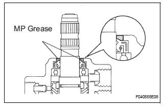
(l) Apply MP grease to the control valve, as shown in the illustration.
(m) Wind vinyl tape around the serrated part of the control valve.
(n) Install the dust cover onto the control valve housing.
11. INSTALL STEERING RACK END SUB-ASSEMBLY
(a) Install 2 new claw washers, and temporarily install the 2 steering rack end sub-assembly.
HINT: Align the claws of the claw washer with the power steering rack grooves.
(b) Using 2 SST, install the 2 rack end sub-assembly.
SST 09922-10010 Torque: 58.5 N*m (597 kgf*cm, 43 ft.*lbf)
NOTICE: Use SST 09922-10010 in the direction shown in the illustration.
HINT:
- Using SST, hold the power steering rack and install the rack end sub-assembly.
- Use a torque wrench with a fulcrum length of 345 mm (13.58 in.).
(c) Using a brass bar and a hammer, stake the 2 claw washers.
NOTICE: Avoid any impact to the power steering rack.
12. INSPECT STEERING RACK END SUB-ASSEMBLY
(a) Ensure that the rack end sub-assembly hole is not clogged with grease.
HINT: If the hole is clogged, the pressure inside the boot will change after it is assembled and steering wheel is turned.
13. INSTALL STEERING RACK BOOT NO.2
14. INSTALL STEERING RACK BOOT NO.1
15. INSTALL STEERING RACK BOOT NO.2 CLAMP
(a) Using SST, tighten the rack boot No.2 clamp, as shown in the illustration.
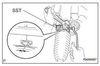
SST 09521-24010 Clearance: 3.0 mm (0.118 in.) or less
NOTICE: Be careful not to damage the rack boot No. 2.
16. INSTALL STEERING RACK BOOT NO.1 CLAMP
SST 09521-24010
HINT: Perform the same procedure on the other side.
17. INSTALL STEERING RACK BOOT CLIP
(a) Using pliers, install the 2 rack boot clips.
18. INSTALL TIE ROD ASSEMBLY LH
(a) Screw the lock nut and tie rod assembly onto the rack end sub-assembly until the matchmarks are aligned.
HINT: After adjusting toe-in, torque the lock nut.
19. INSTALL TIE ROD ASSEMBLY RH
HINT: Perform the same procedure on the other side.
20. INSTALL STEERING LEFT TURN PRESSURE TUBE
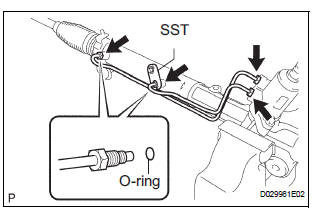
(a) Coat 2 new O-rings with power steering fluid and install them onto the left turn pressure tube.
(b) Using SST, install the left turn pressure tube onto the power steering gear assembly.
SST 09023-38201 Torque: 11.5 N*m (117 kgf*cm, 8 ft.*lbf)
HINT:
- Use a torque wrench with a fulcrum length of 345 mm (13.58 in.).
- This torque value is effective when SST is parallel to the torque wrench.
21. INSTALL STEERING RIGHT TURN PRESSURE TUBE SST 09023-38201
HINT: Perform the same procedure on the other side.
22. INSTALL RETURN TUBE NO.2
(a) Using SST, install the return tube No. 2.
SST 09023-12701 Torque: 22.5 N*m (229 kgf*cm, 17 ft.*lbf)
HINT: Use a torque wrench with a fulcrum length of 345 mm (13.58 in.).
 Inspection
1. INSPECT POWER STEERING RACK
(a) Using a dial indicator, check the power steering rack
for runout and for teeth wear and damage.
Maximum runout:
0.3 mm (0.012 in.)
If necessary, replace t ...
 Installation
1. INSTALL RACK & PINION POWER STEERING GEAR ASSEMBLY
(a) Install the power steering gear assembly with the 2
bolts and nuts.
Torque: 70 N*m (714 kgf*cm, 52 ft.*lbf)
2. CONNECT PRESSURE ...
Other materials:
Camshaft Position Sensor "A" Circuit
DESCRIPTION
The intake camshaft's Variable Valve Timing (VVT) sensor (G signal) consists
of a magnet and MRE
(Magneto Resistance Element).
The VVT camshaft drive gear has a sensor plate with 3 teeth on its outer
circumference. When the gear
rotates, changes occur in the air gaps betwee ...
Map Display Incomplete
INSPECTION PROCEDURE
1 CHECK MAP DISC
Check that the map disc is not deformed or cracked.
OK:
No deformations or cracks on map disc.
2 CHECK DISPLAY
Check that displays other than the navigation display are
complete.
OK:
No other incomplete displays are found.
REPLACE RADIO ...
Diagnosis system
1. CHECK DLC3
The vehicle uses ISO 15765-4 communication
protocol.
The terminal arrangement of the DLC3 complies
with SAE 1962 and matched the ISO 15765-4
format.
If the result is not as specified, the DLC3 may have
a malfunction. Repair or replace the harness and
connecto ...
