Toyota Sienna Service Manual: Reassembly
1. INSTALL LIGHT CONTROL ECU (DISCHARGE HEADLIGHT)
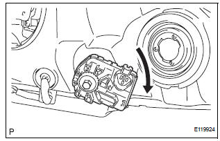
- Install a new headlight leveling motor base packing.
- Install the headlight leveling motor assembly as shown in the illustration.
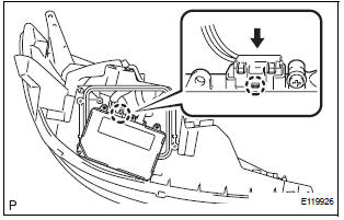
- Connect the connector with the claw
- Install the light control ECU with the 2 screws.
- Install a new headlight gasket.
- Install the headlight cover with the 4 screws.
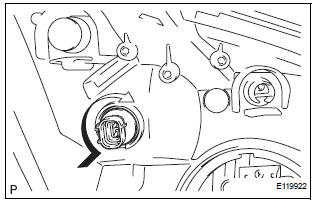
2. INSTALL FRONT SIDE MARKER LIGHT BULB
- Install the side marker light bulb to the side marker light socket
- Turn in the direction indicated by the arrow and install the side marker light bulb and side marker light socket as a unit.
3. INSTALL FRONT TURN SIGNAL LIGHT BULB
- Install the front turn signal light bulb to the front turn signal light socket.
- Turn in the direction indicated by the arrow and install the front turn signal light bulb and front turn signal light socket as a unit.
4. INSTALL NO. 2 HEADLIGHT BULB
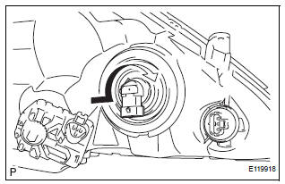
- Turn in the direction indicated by the arrow and install the No.2 headlight bulb.
5. INSTALL DISCHARGE HEADLIGHT BULB (DISCHARGE HEADLIGHT)
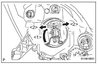
- Install the discharge headlight bulb with the set spring as shown in the illustration.
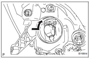
- Turn in the direction indicated by the arrow and install the socket.
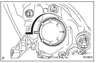
- Turn in the direction indicated by the arrow and install the headlight socket cover.
6. INSTALL NO. 1 HEADLIGHT BULB (HALOGEN HEADLIGHT)
- Turn in the direction indicated by the arrow and install the No.1 headlight bulb.
 Adjustment
1. VEHICLE PREPARATION FOR HEADLIGHT AIMING
ADJUSTMENT
Prepare the vehicle:
Ensure there is no damage or deformation to the
body around the headlights.
Fill the fuel t ...
 Installation
1. INSTALL HEADLIGHT ASSEMBLY
Connect the connectors.
Install the headlight assembly with the bolt and 3
screws.
2. INSTALL FRONT BUMPER ASSEMBLY
3. CONNECT CABLE TO NEGATI ...
Other materials:
SPD Signal Error
DTC 58-43 SPD Signal Error
DTC 80-43 SPD Signal Error
DESCRIPTION
DTC No.
DTC Detection Condition
Trouble Area
58-43
A difference between the GPS speed and SPD pulse is
detected.
Speed signal circuit
Radio and navigation assembly
...
Short to B+ in Side Squib LH Circuit
DTC B0118/46 Short to B+ in Side Squib LH Circuit
DESCRIPTION
The side squib LH circuit consists of the center airbag sensor assembly and
the front seat side airbag
assembly LH (side squib LH).
This circuit instructs the SRS to deploy when deployment conditions are met.
DTC B0118/46 is re ...
A/F sensor and ho2s monitors
(a) Preconditions
The monitor will not run unless:
2 minutes or more have elapsed since the engine
was started.
The Engine Coolant Temperature (ECT) is 75°C
(167°F) or more.
Cumulative driving time at a vehicle speed of 30
mph (48 km/h) or more exceeds 6 minutes.
Air-fuel ratio fe ...
